Monday, 24 September 2012

Coal Tank at CD0GG

Passing through the scenic section of the CD0GG layout


The exterior detail of my Coal Tank, apart from the troublesome tool boxes which I'm still working on, is nearly complete. I took her to the bi-monthly CD0GG Open Day on Saturday for a run on their layout...as you can see, the scenic section is very impressive. The engine ran smoothly with a train of five bogie coaches and could have handled more. She weighs just under 800g, with most of the added weight low down and centred over the drivers.


Coal Tank Crew, Driver on the left and Fireman.


The crew attracted some attention and favourable comment at the CD0GG Open Day and David Gibson snapped a set up immediately. I don't think he has a Coal Tank to put them to work on but these characters can drive lots of different engines, I'm sure you could find a job for them yourself on one of your engines. Both the driver and the fireman are available now in my "Heroes of the Footplate" range; they are...

R21. Driver for a LNWR Coal Tank

R22. Fireman for a LNWR Coal Tank.


Cab detail almost finished.


The most fiddly component in the cab, a part I made myself, was the little vacuum brake valve that sits on top of the backhead. I've not fastened it in place yet as I think I'll have to glue it on...one more touch of the soldering iron I fear and the whole lot might drop to bits! It's connected to the vacuum ejector that sits on the right hand tank top inside the cab by a curved pipe and also connects to the brake valve attached to the outside of the cab front...though I'm still wondering how to make this connection. The brake vacuum gauge is on order and on its way from LGM, this will fit opposite the boiler pressure gauge and that'll just about finish the job... though I've just noticed that the whistle, which protrudes through a hole in the cab roof, needs an operating lever.   

Thursday, 6 September 2012

Cab details and a crew

Part finished cab interior detail
 The cab of a NW Coal Tank is a crowded and busy place. I decided to model the cab detail from the drawing of the cab fittings c.1891 in Peter Skellon's recent book on the Coal Tanks published by the Bahamas Society. This is prior to the fitting of carriage warming equipment which further complicated the interior pipework. Most of the castings I've used in the cab are from LGM, these are invaluable though some need a little modification. I tried to find some suitable commercially available 4ft toolboxes for the engine, without success. So I decided to fabricate a master pattern then make a mould and cast myself a pair in white metal. The pattern sits, as yet unfinished, on the bunker; below is some of the coal, embeded in a Milliput former, which will eventually spill out onto the floor of the cab.


The crew are almost complete.  


The crew are designed to make the best use of a very cramped space, I've based the fireman's pose on  several photos of Coal Tanks with the driver or fireman straddling the cover over the pipework that connects the side tanks to the bunker. The driver in contrast is busy looking through the spectacle plate window and adjusting his cap; his left leg rests on  the top of one of the wooden boxes, provided for the crew to stand on, that flanked the backhead.

The "Crew for an LNWR Coal Tank" will soon be available in my "Heroes of the Footplate" range of 1:43 scale figures.

Saturday, 18 August 2012

NW Coal Tank; recent progress

Balance weights in place beneath the boiler.

Not only are the balance weights in place on the transverse shaft behind the reversing arm but also the whole inside motion is in there between the frames below the weights.  It's cosmetic rather than working inside motion, nevertheless I think it makes all the difference and is a worthwhile addition to the model...well you can judge for yourselves.


Exterior details are mostly complete.

I completed as much exterior detail as time allowed before taking the Coal Tank up to Carlisle to the CD0GG monthly Running Day last Saturday. I'm pleased to say that she ran well, albeit with a train of modest proportion, and was much admired. It was however noted that the engine needs some more weight to help traction and I'll address this matter carefully as I'm wary of adding unnecessary weight to an engine.

  
Interior cab details are still at an early stage.

The roof and rear bunker can be removed at this stage to facilitate work on the cab interior, and there's a lot of detail still to go in there. I'll probably construct a pattern for a tool box myself from which I can then produce a mould to make castings from, as I've not found any appropriate castings available commercially. The wooden brake blocks are LGM brass castings. The pull-rod mechanism isn't complete yet...the actual pull-rods are very fine and I've made them from straightened 1.5mm half-round wire, the half-round profile adds strength without detracting from their appearance.

Thursday, 26 July 2012

Coal Tank's Inside Motion

Stephenson's inside motion with single slide-bars.


Most of the inside motion castings are from LGM with some scratch built additions such as the motion plate and connecting rods. The single slide-bars are from Hobby Horse Developments, the crossheads that slide in them are modified Lochgorm Kits' etchings. The joints which articulated when built have been soldered solid now as this is cosmetic inside motion rather than working motion. 

Inside Motion in place with balance weight shaft mounted above


The balance weights will be mounted on the transverse shaft above the motion plate and will be a be a prominent feature between the frames below the boiler and will mask the inside motion to some extent. The motion unit is designed to allow free movement of the front sliding axleboxes. The black wires are the pick up wires taking current from the front axleboxes to the motor.


A busy place between the Coal Tank's  frames

The camera hasn't done justice to the inside motion in this shot, I think that when the balance weights are added the effect will be more striking.


Coal Tank cab and bunker, exterior detail almost complete.

The cab side-sheet beading was made from rectangular stock soldered on and filed to shape. The water filler was scratch built from so many parts that I decided to glue it in place in case it auto-destructed with the next touch of the iron.

Saturday, 7 July 2012

Coal Tank pick-ups


Coal Tank showing pick-up arrangement on front bearings.
The front driving wheels do not lend themselves to wiper pick-ups such as I fitted to the other drivers because the frames are cut away at the front and there's really nowhere to mount them. To circumvent this problem I used a split-axle system. The front axle is a split-axle which is carried in Slaters' 7961 Hornblocks (insulated bearings). The axle runs in square brass bearings which slide in the black plastic insulated hornblocks. You can see the pick-up wires soldered to the bottom of the brass bearings, they then snake through the motion plate to make their way back to the motor while keeping out of the way of the inside motion above. Only the slide-bars and motion plate are in place, forming the basis of the inside motion unit, which at this stage can be removed. The design of the chassis is evolving gradually; somehow, when I eventually get it right, it looks so simple and obvious.

Monday, 18 June 2012

Vacuum pipes, a solution?

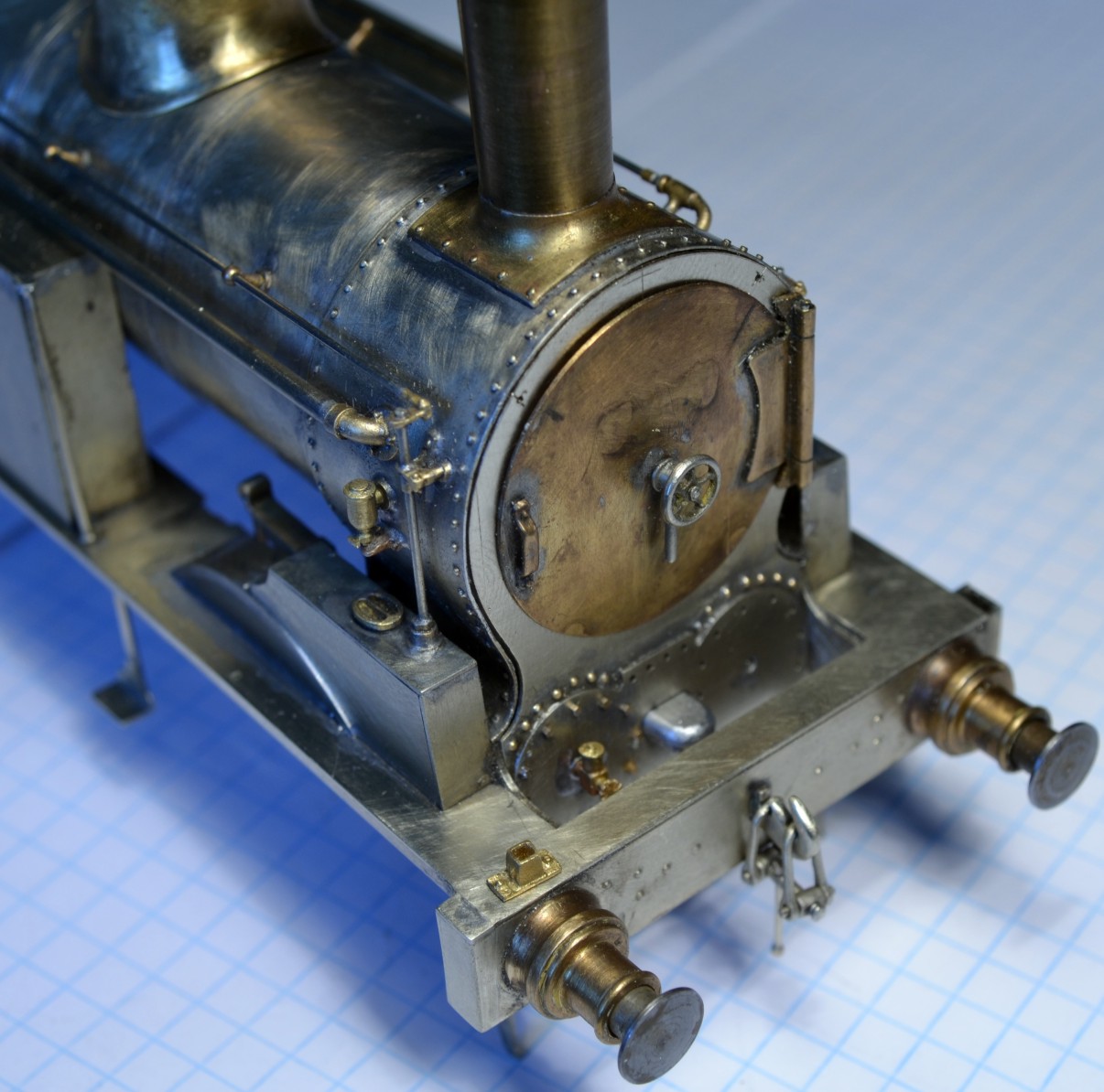
Coal Tank front complete with scratch built vacuum pipe
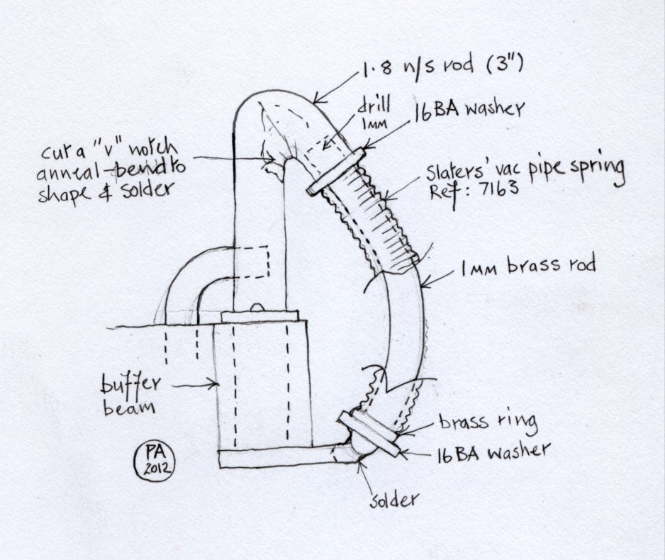
I used lost wax lamp socket castings from Gladiator Kits which are to scale and will take the square pegs of model LNWR loco lamps; cast brass ones can be obtained from LGM; white metal ones are available from my own "Heroes of the Footplate" range, Ref: LT3. The superstructure of the engine is practically complete now, though the cab interior detail needs much attention as does the chassis. The vacuum pipe uses one of Slaters' Vac Pipe Springs Ref: 7163 and is constructed in the manner shown in the accompanying drawing. The rear vac pipe appears to be rather more of a challenge.


Drawing to show construction of vacuum pipe
   

Friday, 8 June 2012

Coal Tank progress

Front of Coal Tank showing cylinder covers under construction
When I put the cylinder covers in position I discovered that the semi-circle of rivets above them was in the wrong place, so I had to cut a new smokebox front. This time I elected to fix the cylinder covers in place then used dividers to mark out the position of the offending rivets. I drilled holes in the appropriate places and soldered 0.8 rivets from Scale Hardware into the holes. The cylinder covers similarly are drilled to accept Scale Hardware 0.7 hex bolts. The cast brass cylinder head lubricators are from LGM, here only the right hand one is in place, the left hand cylinder head is as yet unfinished. In the centre is the valve spindle cover.
Above the right hand buffer I've positioned an LNWR pattern lamp socket, which I've opened out to accept the tapered square peg of the lamp. I've not been able to locate a source for castings of the other patterns of lamp socket that were used above the smokebox door and on the bunker rear yet. I need them to scale so the loco lamps will actually fit into them