Tuesday 29 December 2020

HR Swivel Cradle Wagon Resin Parts in 7mm scale.


These accurate 7mm scale resin castings are designed to take the strain out of building a HR swivel cradle wagon, they are not a complete kit, they are aids to scratch building, they are the difficult parts of the wagon. Everything else needed to complete the multi media model can purchased from the trade or can be simply hand made. Below I'll show you how I completed the wagon, my build is not compensated, there are no rocking w-irons or sprung axleboxes, however these could be contrived, it's up to you how you complete the model.

Price for one set of resin parts...£22.50 plus p/pkg at cost £1.50

Order a pair and it's post free.

Order 3 or more and discount is 10%. 

Contact Pete on...

armstrongps1@gmx.com

07342 637 813

017687 71302

Or by mail at..

21 Manor Park

Keswick, Cumbria,

CA12 4AB


The wagon bed is made from Slaters 7mm planking glued to a thickening sheet of 1mm Plastikard. The deck fittings are made from the drawings of this wagon on page 161 in Peter Tatlow's book, Highland Carriages and Wagons, the drawing is essential in order to complete the wagon. Buffers are HR single web type available from Invertrain. The underframe cross members are made from Plastruct 90779 styrene strip, the central section has a sheet of lead inserted for weight. The brake lever suspension point is only needed on one side so the extra one is removed.


The cradle is in place on the wagon bed, the brass corner eye bolts were purchased from Prime-Miniatures. I made a stanchion by turning a length of rod to shape using a file and an electric drill, the little eyes for the retaining chains were added later. I suppose I could have made all four this way but as I had some silicone rubber to hand I made a mould and cast the rest. Tensioning rods, made from 0.6mm nickle silver wire, can be seen in place alongside the cradle side members. The cradle swivels on a central 12BA brass nut and bolt.


I made two wagons as examples as I think they probably worked in pairs in service. The combined w-iron, spring and axle box castings are from my own master patterns, cast in silicone moulds in my workshop. It's a simple expedient and both wagons run very well indeed without compensation. Couplings are hand made, the hook being cut from 1.25mm nickle silver sheet and the links formed on a jig from 0.8mm wire. Suitable couplings, which match the square holes in the buffer beam, can be obtained from CPL. Horse hooks are brass castings which I source form 62C Models along with the brake lever guides, which can be seen to better effect below. I have added a few holes and the pin, which goes into these, dangles on a fine chain attached half way up the guide.


The simple one piece castings were drilled for Slaters' axle bearings then glued to the solebars with the axles in place, providing the axles are parallel in all planes the wagon will run smoothly. Castings similar to these can be obtained from Invertrain.


The brake arm and shoe was cut from 0.7mm n/s sheet and the brake lever from 0.45mm n/s. Retaining chains have been added to the stanchions and the chains, turnbuckles and hooks that secured the load can be seen attached to the corner eye bolts, these can be obtained from CPL Products.  


Watch this space for a picture of the painted wagon complete with number plate. 


Friday 23 October 2020

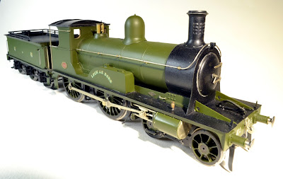
HR 123 Loch an Dorb.


Loch an Dorb, from the Gallic meaning possibly Loch of the Minnows or more likely Loch of Troubles. The model is complete now apart from coal in the tender which I have in hand. The basic colour is Precision P727 which is now no longer available, I only have enough left for touching up now. Etched number plate, name and buffer beam transfers are from Guilplates, the latter are no longer available either. Footplate crew are my own sculpture, designed for this particular engine and now available from Invertrain. 


The cab interior is as complete as I can make it, I took the details from the drawing in Peter Tatlow's "A History of  Highland Locomotives". The backhead casting and many of the small fittings are from LGM though both have been modified to suit. 


Cab interior and crew with the roof removed for a better view of the works.


The superstructure owes a debt to some specially commissioned nickle silver etches from Lochgorm Kits, the chassis however was scratch built. Wheels are cast and turned by JPL Models as Slaters have no correct ones in their list. Motive power is provided by an M1833 motor mounted in an ABC Gears Mini Gooch gearbox. Loch an Dorb's debut on the club layout in Carlisle will be much delayed I fear by the renewed Coronavirus outbreak, I won't be going up to the clubroom this side of Christmas and probably for some months after, neither will I be able to photograph her in a realistic setting hauling a train, she'll just have to wait.

Saturday 19 September 2020

Resin Sides for a 7mm scale HR Ballast Wagon


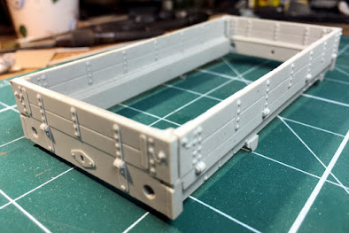
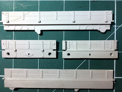
After building a couple of ballast wagons the hard way, as I described in previous posts, I decided to investigate a quicker way to build a wagon as I needed a few more to make my ballast train more credible. So, in collaboration with a mate who specialises in model aircraft kit accessories, I produced these interlocking resin sides and ends. The floor, "w" irons, wheels, buffers, couplings, axle boxes, springs and brake gear are not supplied but are all readily available from the trade. 

The castings are available for purchase at £20 per set + post/packing at cost £1.50 (UK).

Contact Pete on...

armstrongps1@gmx.com

07342 637 813

017687 71302

Features.

There is an inner step between the side planks and the solebar which it is intended that the wagon floor sits on. If this is made from sheet metal then the "w" irons can be soldered beneath which makes for a robust construction. The metal floor can be faced with Slaters' 7mm Plastikard planking to make a convincing wagon bed for an empty wagon. 

The sides and ends are scale 3" thick and interlock to facilitate construction.

The draw plate has a square hole to take a CPL wagon hook (my preference) , or you can scrape the draw plate off and replace it with a different plate and hook.

There are downward projections mounted on the solebar to which the brake lever and brake handle are fixed, they are designed for Drummond's patent each-side brake gear. It's quite a simple matter to make the parts needed from 0.45mm brass or nickle silver strip using Peter Tatlow's drawing in "HR Carriages and Wagons" as a guide. 

The fastening that holds the drop sides and ends in place, along with its chain are part of the casting,  which saves a lot of time and fiddling.


Thursday 20 August 2020

HR Ballast Wagon No. 2745

 No. 2745 built 1901/2

No.2745 with ballast load and modified buffers with end-door stops added.


In early 2018 a Highland Railway Society member sponsored the production of a short run of cast resin ballast wagon bodies which were well mastered and cast by JLTRT, they  were accompanied by an etch for the W irons and brake gear. I missed these at the time, being too busy with other projects, though I managed to acquire recently what must have been one of the last resin bodies available, though without the etch which I believe was rather wayward in any case, a “curates egg“ according to one comment I read at the time. 

The resin body was crisply moulded and promised a less laborious path to a ballast wagon than my previous all metal conversion. I added the fine chains that held the staples that fasten the sides in place from twisted fine wire. I made the brake lever and the support bracket, on which it pivots, and made a similar support for the Drummond both-sides brake handle. These parts were made from o.45 nickle silver sheet and were glued into slots cut in the underside of the solebar. I used sprung w-irons from Slaters, white metal springs from Invertrain, axle boxes from Lochgorm and sprung 3-link couplings from CPL, so an eclectic assortment of fittings went into completing the model. All metal to resin joints where practical were pinned and glued for security. 

I decided that this wagon would not only complement 2525 but would contrast nicely with it if it was provided with a ballast load. I made this from Milliput which was shaped to fit inside the wagon as a former to which the actual ballast was glued with woodwork glue, this was Carrs' Ballast 7mm Light Grey. I glued lead sheet under the wagon bed to bring the weight up to 150g, equal to the weight of the all-metal version. 

Ballast wagon buffers have a single tapering fin on the outside and feature end-door stops cast on the upper part of the housing. I used HR wagon buffers from Invertrain’s range and added end-door stops from thin slices of appropriate sized “U” shaped brass, which I soldered on top with ultra low-melt solder.

The wagon was painted similarly to 2525 with Precision P963 Dark Brick Red, HRMS transfers competed the colour scheme.


Ballast wagon No. 2747 in 1938 displays Drummond patent braking gear, and an absence of safety chains. A canvas flap, which prevented dust entering the axle box, is in evidence. A photo of an Engineering Dept. ballast wagon in later days (D297205) shows a U shaped metal plate guarding the near axle box though nothing over the rear one. Photo... D.L.G.Hunter from Carriages and Wagons of the HR. 


Monday 20 April 2020

HR Ballast Wagon Complete

Highland Railway Type J 8 ton drop-side ballast wagon 

The model was built with the aid of an etched brass kit from Lochgorm Kits' for a 4-plank open wagon, from which the model was converted with the addition of extra parts. It seemed simple enough at the outset but turned out to be a laborious and time consuming way of producing a ballast wagon. A limited number of resin bodied ballast wagon kits were produced recently by a Highland Railway Society member and I'm sure these would make a very nice model in rather less time than the road I took. Though I prefer all-metal construction, a quicker build second wagon to make a pair, one empty and one with a load, is a temptation.

I printed the oval number plate on the sole bar myself on an inkjet from my own artwork. Transfers are from HMRS sheet 20. The basic colour of the wagon is Phoenix Precision P963 Dark Brick Red. I used this colour as I've run out of Caledonian Goods Wagon Oxide, which I usually use, it seems to be more or less the same colour.

The inside of the wagon was painted with Humbrol matt 110, a light brown colour, this was dry brushed dark to light. The ironwork was painted matt black then this and the planking was lined with thin black paint which flowed round the detail and into the intaglio by capillary action.

A residue of ballast chippings and an old sweeping brush add interest to the interior.


Sunday 5 April 2020

Highland Railway Ballast Wagon

HR 8 Ton Ballast Wagon Type J diag. 23 

My starting point for this model of a Highland Railway two-plank drop-side ballast wagon was a Lochgorm Kits' four-plank open wagon kit. The wagon sides were thickened to scale by using a spacer between the inner and outer walls, the hinges and strapping were cut from strip then shaped and soldered on in the flat, both inside and out, before the wagon was assembled.

The black dots you can see on the ironwork of the wagon body are Archers' Surface Details resin rivet transfers which seem to have adhered reasonably well to the nickle silver strapping, those that came off I stuck back on with varnish. The trick I employed when using them was to place the transfer dry on its backing next to the hinge or strap and then wet it and slide the rivet strip into place. The undercoat should help fix them too, I intend to use Halfords' Acid 8, which doesn't seem to have any adverse effect on them.

The wagon is fitted with Peter Drummond's patent each-side brake mechanism, so there's a handle on the other side as well, though no brake lever. Safety chains are fitted too so the model must date between 1896, when Drummond took office as the Highland's Locomotive Superintendant, and 1900 when safety chains were dispensed with.

The wagon is number 2525, though the wagon plate is not ready yet. I've drawn the artwork for the plate which will be scanned, sized and printed then glued to a backing and cut to shape. However the printer's out of ink and I'm waiting for a delivery, which is slow at the moment.

All the pictures I've seen of these wagons have buffer housings with a cast stop on top for the wagon end to drop onto. I could find no commercial casting for this type so I made my own by soldering a block of scrap white metal onto each housing then drilling them and shaping them with a knife and files. You'll need an Antex White Metal Master soldering iron for this job and some ultra low-melt solder. And of course solder the buffers to the wagon body first before adding the stop.


Underneath from the rocking-axle end

This view of the un-prototypical underside shows the cut-aways in the rocking-axle tray that have been made to allow the sprung draw-hook and buffers to operate. The transverse rod links the handles of Drummond's patent both-sides brake gear.


Sunday 29 March 2020

Jones Tank bogie rebuild.

HR Jones Tank No. 58 after her repairs

At the February Running Day on the CDOGG layout in Carlisle my Jones Tank, which was built some time ago did not run at all well, in fact she failed to negotiate the circuit at all. I thought it was partly a problem with the front bogie and partly due to the vagaries of the track, particularly where the lifting flap provides a testing unevenness, which has been the ruin of the pretensions of many a poor engine. My misgivings about the track were however unjustified in this case as examination of the offending bogie running on my test track at home highlighted the fact that the rear wheels were not even revolving! The problem proved to be entirely a bogie malfunction. Closer investigation showed that the frames had somehow expanded and were actually breaking away from the horizontal stretcher and locking the back wheels. There was a good deal of lead weight glued into the bogie between the frames and I could only surmise that, depite my using Araldite epoxy glue, expansion of the adhesive was somehow to blame.

The engine started life as an aged Jidenko/Shedmaster kit, described by Laurie Griffin himself as "a difficult kit" and difficult it is, nearly impossible actually, without a great deal of modification and improvisation. The bogie frames were, on examination, found to be only 0.45mm thick, too flimsy for frames really. In addition, the mudguards on the front bogie wheels had always been a problem, the restricted clearance causing them to foul the cylinders and front buffer beam. Though this did not result in an electrical short circuit, as the wheels are insulated from the mudguards, it did not improve the engine's running characteristics. I resolved to simply scrap the old bogie and build a better one and see if I could improve clearances at the same time.


The mudguards are clear of the cylinders now though it's still tight.

I cut the new bogie side frames from 0.7mm nickle silver and built the bogie solid, without compensation. The earlier version had enjoyed the complication of hornblocks for the rear wheels to slide in, which I decided to scrap in favour of simplicity, relying on the central pivot of the bogie to provide articulation in all planes. I omitted most of the lead weight, adding only a modest amount this time. I was able to re-use the mudguards, though I remodelled them as tight to the arc of the wheel as possible and though I probably managed to pinch less that a millimetre, it made all the difference and the rebuilt bogie ran visibly clear of the buffer beam and the bottom of the cylinders. I made new guard irons, bending them and their support from a single strip to replace the earlier multi-part lash-up, not only providing a more robust solution but also an improved appearance.

The engine runs well now, at least it does on my own test track in the studio, taking the 6ft radius curves in her stride. An ABC Gears' Mini Gooch gearbox with an 1833 motor and flywheel, which I deem essential if space allows, ensures smooth running.

My aim when building a locomotive is that it should perform well in a "club layout situation" and these repairs should ensure that it does just that. However, due to the ongoing deadly virus crisis, her test run on the club layout in Carlisle is postponed indefinitely...


Rebuilt mudguards and guard irons, note clearance under buffer beam is tight.

Tuesday 10 March 2020

Dunrobin, construction complete.

Construction of Dunrobin is complete, note that all the fittings are cast brass. The brass nameplate displays the name in incised letters, it was etched by Narrow Planet.


Construction of Dunrobin is now complete, here are a few photos of the engine. Painting and lining will I hope be undertaken by Paul Moore, though I'll probably paint the cab interior and its details myself. The crew will be from Invertrain's Heroes of the Footplate range, which I sculpted myself, and I might paint a figure or two to go in the cab seats too.


Much buffer beam detail was added, brass rivets, safety chain suspension rings and horse hooks.  
Tank top inspection panels were added from photos from Beamish. Note the quality brass fittings.


Below the footplate is a busy place, the sandbox and the iron picnic box above the rear bogie wheel are brass castings.


I have added all the detail to the cab interior that I have evidence for, though I have omitted all the Canadian fittings which have also been removed from the real engine.


There is seating for four passengers above the coal bunker.


Dunrobin is due to be in service at Beamish in 2021, however I hope that my model will be painted and lined and in service herself before then.

Monday 24 February 2020

Dunrobin...More progress

Boiler backhead in place with modified fire hole door
I had help from Paul Jarman at Beamish museum who supplied some photos of Dunrobin which clarified most of the details of the cab interior. I'm still not sure about my positioning of the Dreadnought vacuum ejector, which you can see sitting on the right hand inner tank top, behind the reversing lever. The original ejector was removed in Canada when Westinghouse braking equipment was fitted; it languished on a shelf in a workshop there, where fortunately it remained until its repatriation along with the engine in 2011. Apart from the ejector, which is provisionally positioned at the moment, the inner tank tops are at this stage still bare of equipment, though I'm sure that evidence will emerge of detail which can be added to enliven this area. The cast brass backhead supplied in the kit has been modified so the firehole is now correct with horizontal sliding doors and operating lever at floor level.

Photos from Beamish and a GA drawing of the cab area from Sharp Stewart the builder, provided the details for the seating in the cab rear. There are duckboards for the passengers' feet and a padded seat, which are above the coal space, the coal door is central at floor level. On the rear wall of the cab, above the windows, can be seen a coat rail; between the windows there should be a set of framed autographs of distinguished passengers, details of which I have yet to clarify.


Cab rear with seating for four people with coal bunker below.


Dreadnought ejector sits on the tank top connected to the ejector pipe which can be seen through the window.

Some of the castings for the boiler backhead are taken from the 4mm scale version of the engine which were rather over scale. Other cab details including the reversing lever and brake standard were constructed by the author. On top of the backhead sits a handwheel, a detail which I hope to enlarge on as my understanding of the cab controls and gauges develops. The wooden floor is constructed from model ship planks and is in two parts, left and right, to allow for removal. The mechanism for operating the tablet catcher is fixed to the end of the left hand inner tank. Note the inner sliding cab windows which are single skinned and will eventually be glazed by simply affixing a sheet of glazing to the rear after painting; the handles for these windows will glue to the glazing.


Tank tops and ejector pipe are well seen in this view.

The original ejector pipe was removed in Canadian days so I have relied on photographs to restore it to its correct position. It kinks towards the boiler after leaving the smokebox and is supported from the boiler just after the bend.  After running along the boiler towards the cab, the evidence of a hole in the cab front plate suggests that the pipe crossed over the tank top towards the outside of the engine to enter the cab and connect with the Dreadnought vacuum ejector inside.
Narrow Planet provided the etched nameplates.
The tapered buffer housings, which have a square base, were modified from a set of Slaters' GWR buffers but are still a couple of scale inches longer than the prototype's miniscule 9 inches.


Brass castings for rear sandboxes and picnic hamper boxes are soldered to frames.

Roof in place emphasises the large space occupied by the cab.

Monday 20 January 2020

Dunrobin...Progress.

Dunrobin superstructure, parts in nickle silver are replacements or additions by the author

The cab sides needed the top rail above the cab door thickening and the only way I could do this was to replace the whole side. I'm working on the new sides in the flat, adding the inner sliding windows which completely enclose the cab when closed. The separate assemblies of the engine, the boiler and smokebox, the tank and cab sides and the footplate and cab interior, will be assembled when the interior is as complete as I can make it. The stepped seating arrangement in the cab rear is based on photos taken at Beamish, after Dunrobin returned from Canada. I have a couple of pictures of part of the inner cab front plate and the top of the backhead, though I the suspect that some of the equipment in the pictures was added in Canada and is not relevant to a model of the engine in original condition.


Part of the frame will be removed behind the front bogie wheel to allow the bogie free movement

Cab interior showing inner sliding windows and right hand drive reverser.

The cab of Dunrobin is generously proportioned because of the seating at the back of the cab and I plan to fully detail the interior though I have not yet obtained all the information I need to complete the backhead and other details at the front of the cab. I have a useful side elevation drawing of the cab, which shows the reverser well and allowed me to model the lever and its ratchet frame. On the opposite side of the cab, the fireman's side, stands a handbrake stanchion for which I also have information enough to make one.

An important consideration in building Dunrobin was the manner in which the cab windows were to be glazed to look convincing not only from the outside but from inside too. My solution was to double-skin the cab sides to allow the glazing to slide between the outer and inner skins. The sliding inner windows are a single layer with glazing glued behind them with ZAP canopy glue, which dries clear. These windows slide in 1mm U section brass, soldered inside the cab sides.
I decided not to double-skin the cab front and rear plates due to the presence of those etched ventilation slots high up between the windows, these I could not reproduce on the cab inner with any accuracy, so single skin they remain and I think they are more convincing as they are.

The driver's door on the right hand side is modelled closed because the driver will be positioned there leaning on door and looking out of the cab. The left hand cab door will be in the open position to allow a good view of the cab interior detail, the inner sliding windows will also be open.


ABC Gears triple reduction gearbox with 1625 motor  

Power is supplied by an ABC Gears "PUG" gearbox, designed for small prototypes, the 1625 motor drives the fixed rear axle through a triple-reduction gearbox.  The mechanism sits upright in the firebox and fits inside the diminutive 3ft 9" diameter boiler very neatly. Wire pick-ups bear on the rear of the wheel rims on the left hand side and on the right are shorted by means of an 0.5 wire running in a spoke, which connects the brass central hub to the wheel rim.