Friday, 20 January 2017

A Crew for a HR Loch.

Crew seen with the roof removed

With the roof in place the cab interior is still a focus of interest and detail.


Little of the backhead detail is obscured by the crew.

Fitting figures into cabs so they don't fall over...How to do it...As construction of my HR Loch approached completion I turned my attention to providing a suitable a crew that would fit the cab without unduly obscuring the backhead detail or appearing to crowd the rather restricted cab area. You can judge for yourselves the degree to which I've succeeded. Both the figures are fixed in place with short lengths of brass rod. The driver on the left of the engine has a short 0.6mm dia. rod fixed in his bottom which locates in a corresponding hole in the splasher top. The fireman has a similar rod inserted into a hole drilled through his foot and up his left leg which locates into a hole in the cab floor. The figures are securely in place and do not fall over when the engine is in motion. I'm sure that this is the best method of fixing figures in place in cabs, they can be removed at will and the tiny locating holes are hardly visible.

Both these figures, which I designed with the cab of a 4-4-0 in mind, are now available from Invertrain

Sunday, 4 December 2016

HR Loch an Dorb progress.

HR Loch class tender original length though without rear toolbox.


The main structural components of the tender are from the Lochgorm kit though the tank corners and curved coping are sections cut from brass tube as I could not bend the material of the kit, the coping was too intransigent and the corners kinked when I tried to bend them due to the oversize holes for the corner handrails. The steps still need improvement to remove the etched outlines above the horizontal part of the step.


HR123 in 1923. Courtesy of the Highland Railway Society.


A rear view of Loch an Dorb at Blair Athol in 1923 in the HR collection at Am Baile shows her running with an original tender with a rear toolbox. However the above picture, which I believe was taken in either 1923 or shortly after, shows her in HR livery with what I interpret as an original length tender though with the rear toolbox removed. A shorter one can be seen mounted behind the driver. The tender has at this time not yet been lengthened to the full length of the footplate. This is the style of tender that I've modelled (above). 
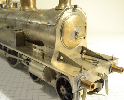


Smokebox and footplate detail

The inspection covers above the slide bars were represented on the footplate by an unsightly etched outline. I cut along the etched lines to create a rectangular hole in the footplate and made an infill to represent the covers which just need some tiny hinges to complete the effect. There may be something available in Archer Surface Detail transfers that will fit the bill.


Cab roof constructed from nickel sheet silver with brass extruded cross ribs. 


The roof is made from sheet nickel silver though the front curve is a section of brass tube, transverse ribs are extruded brass section. The tablet catcher on the cab side is an LGM casting to which I've added a handle that protrudes into the cab.


Detail of cab and backhead with roof removed.


There are three sources of information for the backhead detail; a drawing by Peter Tatlow; a GA of the 1917 engines and of course the backhead of the preserved Jones Big Goods in the Transport Museum in Glasgow. Though I've mainly based the details on Tatlow the other sources have helped too. Castings are mainly LGM, some of which are a little oversize, they have been reduced to the right scale with an unavoidable though slight loss of detail.

The oversize inside splashers contribute to limit the space available for a crew, which in the case of a 4-4-0 with so visible a cab interior, I consider mandatory.

The fall plate is attached to the engine and because of the protruding side wings and stanchions on the tender footplate I've had to make the fall plate cut-outs oversize to accommodate these as there is a good deal of movement between tender and engine on corners. Fall plates and tight corners are not compatible and neither I suspect are cab doors, particularly the bi-fold variety that the Lochs carried, though this is a problem I've not yet examined closely.
I don't think the engine will ever be happy running in reverse, however as the Highland did not encourage this practise it shouldn't present a problem.  

Thursday, 27 October 2016

HR Loch Valve Gear

HR Loch chassis progress so far.


The Loch class employed Allan's Straight Link valve gear and the parts and castings to build this feature are readily available from LGM.

The valve gear is suspended from the links that depend from the reversing shaft levers which are situated above the radius link on the reversing shaft.

The forked ends of the eccentric rods attach to the straight radius link in which the jointed valve rod pivots, these parts were assembled to form two separate units. This part of the valve gear is fairly easy to fathom from available drawings and is intended to work, the eccentrics will motivate the radius link and the attached valve rod will move horizontally.

More obscure is the manner in which the valve gear is supported from the reversing shaft lever above and this is where the model and prototype are going to have to go different ways as I don't think it feasible, at least not without huge effort, to model this feature of the valve gear according to prototype.

The lifting links depending from the reversing shaft levers will not be attached to the valve rod and radius link prototypically, they will remain cosmetic. They don't move anyway, at least not much, other than when the valve gear is reversed.


Allan's straight link valve gear rear view from above.


The complexity of the arrangement of links depending from the reversing shaft levers is evident in this view, the rear lifting link attaches to the forked end of the rear valve rod. The front lifting links attach to the radius link.  All the parts are now in place though the lifting links are not attached to the valve gear, they remain cosmetic.


The reversing shaft levers are mounted on the transverse reversing shaft just behind the motion plate.


Loco body in place showing the gap under the boiler through which the valve gear can be seen.


When your eyes accustom themselves to the murk under the boiler and you get in close there's still not a lot to be seen through the gap between boiler and frames. Most of the movement will be in the gloom behind the motion plate...and Yes, it has occurred to me that inside motion in this case might not be worth the time spent on it.

Sunday, 25 September 2016

HR Loch 4-4-0 Chassis Details

HR Loch class 4-4-0 chassis detail


The chassis frames are cut from 0.7 nickle silver sheet. The slide bars and connecting rods are from Laurie Griffin though they have had to be modified to suit the engine. A start has been made on the inside motion which is Allan's Straight Link Motion which is somewhat different to Stevenson's motion. Behind the motion plate can be seen the reversing shaft from which are suspended the levers to which are attached the lifting links that support the valve gear. Eccentrics will be mounted on the front driving axle...at least that's the plan at the moment! I await parts from LGM to enable more progress.


Loch chassis with superstructure in place.


The superstructure is mounted on the chassis here so you can see the position of the M1833 motor which will have to run without a flywheel as there's just not room for one inside the boiler when the motor is mounted upright on the rear axle. The motor is held in place by a fork mounted on the cross member which allows some movement...as recommended on the ABCgears website. There is room to add some weight to the chassis in front of the motor.
The 14BA screws retaining the front axle bearing in its slot can be seen, the axle needs to be dismountable so that the eccentrics and their straps can be fitted. These will be supported by the links depending from the brake shaft (or will appear to be) and the valve rods will pass through the motion plate and locate into a gland in the valve chest. The forked end of the brake lever can be seen on the left of the brake shaft passing behind the splasher.


Saturday, 24 September 2016

NBR Covered Van

NBR Covered Van from a Parkside Dundas kit.

I ordered this Parkside Dundas van by mistake, my intention being to purchase an NB open wagon, of which more later. I took the kit on holiday with me to Co.Wicklow and worked on it as much as I could in a gloomy corner of our holiday cottage during the evenings. Later, in better light in the studio at home, I replaced the rather clumsy brake gear with parts I made myself. I also did some artwork for a wagon plate which I printed on the inkjet as described previously in this blog on 10/2/2016 in "Wagons and Wagon Plates". I used transfers from HMRS as these have no surrounding film and definitely give the best results. Apart from the brake gear and the addition of door chains and a little weight the kit is built as supplied and despite being less than an enthusiast of plastic kits I'm quite pleased with it.   

Wednesday, 24 August 2016

HR123 Loch Class 4-4-0 Progress

HR123 Loch an Dorb


I bought only the superstructure kit from Lochgorm Kits, the chassis I decided to scratch build to my own design. All castings are lost wax cast brass and have been sourced from Laurie Griffin at LGM.
A substantial number of the etched components in the kit have been replaced with parts that I've made myself. The boiler as supplied had rather oversize bands so was the first item discarded followed closely by what seemed to be a rather clever cab interior fold-up which it proved on closer inspection was better replaced by something nearer the real thing. The boiler backhead was scratch built as LGM had run out of castings of this item; making this was quite a mini project in its own right. The boiler castings, chimney and dome that is, are very good however the safety valve casting leaves much to be desired, the upright valves are too far apart and too slim, and will need working on.

Wheels with the correct crank pin position are only available from JGM, these are cast iron ones which it seemed a good idea to try. As supplied the wheel castings needed a good deal of work to clean up and still need attention with some sort of filler here and there, I doubt that I'll go down this road again.

Power will be provided by an M1833 running in an ABCgears Mini gearbox which will be mounted on the front axle, pointing backwards towards the cab, which just leaves room for a flywheel which I consider essential, the running qualities of the engine being paramount.
Inside motion is a possibility however I'm not sure at this stage whether to complicate matters further, you can't see much under the boiler.


HR Loch Class cab details.

Thursday, 4 August 2016

Four Recent Scottish Wagons.

GNoSR coal wagon

Built from a Dragon Models/Celtic Connections kit with minimal improvements, though I did make a wagon plate from a hand drawn original, sized on the computer and printed on the ink jet. Though flat, without relief, these "trompe l'oeuil" printed wagon plates nevertheless fit the bill nicely. The coal load is real coal laboriously glued with thin wood glue to a Plastikard support.


HR d.6 coal wagon

Built from a recently issued Lochgorm Kits "aid to scratch building" with a good many improvements to the basic etches, addition of a printed wagon plate and coal load. The wagon sides were thickened to scale with Slaters' Plastikard planking which was glued to the interior; the join along the top edge of the wagon was disguised by the addition of a thin metal strip which was soldered to the top of the outer skin and slightly overlapped the inner.

I painted all three of the HR wagons with Precision Paints' P953 Dark Brick Red (Matt), transfers are from HMRS. Weathering was by hand dry brushing helped along by a judicious air brushing of my own weathering mix and a good deal of scrubbing with a stiff bristled brush.

HR d.15 open goods wagon.


The HR d.15 wagon above is described in an earlier blog posting of March 2016 and is included for comparison with the d.16 open goods wagon below which is built with the help of Lochgorm Kits' recently produced kit for a d.16 open wagon; it is 6" longer than the d.15 above and displays a number other subtle differences of detail which give interest to the pair of opens.


HR d.16 open goods wagon.