Monday, 20 January 2020

Dunrobin...Progress.

Dunrobin superstructure, parts in nickle silver are replacements or additions by the author

The cab sides needed the top rail above the cab door thickening and the only way I could do this was to replace the whole side. I'm working on the new sides in the flat, adding the inner sliding windows which completely enclose the cab when closed. The separate assemblies of the engine, the boiler and smokebox, the tank and cab sides and the footplate and cab interior, will be assembled when the interior is as complete as I can make it. The stepped seating arrangement in the cab rear is based on photos taken at Beamish, after Dunrobin returned from Canada. I have a couple of pictures of part of the inner cab front plate and the top of the backhead, though I the suspect that some of the equipment in the pictures was added in Canada and is not relevant to a model of the engine in original condition.


Part of the frame will be removed behind the front bogie wheel to allow the bogie free movement

Cab interior showing inner sliding windows and right hand drive reverser.

The cab of Dunrobin is generously proportioned because of the seating at the back of the cab and I plan to fully detail the interior though I have not yet obtained all the information I need to complete the backhead and other details at the front of the cab. I have a useful side elevation drawing of the cab, which shows the reverser well and allowed me to model the lever and its ratchet frame. On the opposite side of the cab, the fireman's side, stands a handbrake stanchion for which I also have information enough to make one.

An important consideration in building Dunrobin was the manner in which the cab windows were to be glazed to look convincing not only from the outside but from inside too. My solution was to double-skin the cab sides to allow the glazing to slide between the outer and inner skins. The sliding inner windows are a single layer with glazing glued behind them with ZAP canopy glue, which dries clear. These windows slide in 1mm U section brass, soldered inside the cab sides.
I decided not to double-skin the cab front and rear plates due to the presence of those etched ventilation slots high up between the windows, these I could not reproduce on the cab inner with any accuracy, so single skin they remain and I think they are more convincing as they are.

The driver's door on the right hand side is modelled closed because the driver will be positioned there leaning on door and looking out of the cab. The left hand cab door will be in the open position to allow a good view of the cab interior detail, the inner sliding windows will also be open.


ABC Gears triple reduction gearbox with 1625 motor  

Power is supplied by an ABC Gears "PUG" gearbox, designed for small prototypes, the 1625 motor drives the fixed rear axle through a triple-reduction gearbox.  The mechanism sits upright in the firebox and fits inside the diminutive 3ft 9" diameter boiler very neatly. Wire pick-ups bear on the rear of the wheel rims on the left hand side and on the right are shorted by means of an 0.5 wire running in a spoke, which connects the brass central hub to the wheel rim.

Thursday, 26 December 2019

Dunrobin, Making a Start.

Dunrobin frames under construction

Lochgorm Kits' 7mm kit for Dunrobin, the duke of Sutherland's private engine, was I believe designed originally in 4mm scale by Alastair Wright of 5522 Models and enlarged to 7mm by the late Andy Copp when he took over production of the former's Highland Railway kits in 2011. Alastair began introducing Highland Railway designs to his range in the 1980's; these were hand drawn and, though not designed for 7mm, when enlarged they served well enough though they took their faults with them to the larger scale and magnified a number of these, so some of the etched parts of this kit need to be remade with more accurate replacements.

The chassis (above) is etched in sturdy 0.7 nickel silver and the frames are a respectable 26.4 mm outside diameter so I had to file a bit off the frame bushes to free the wheels. I've introduced a few more cross-members for the cylinder front and rear and for the ash pan. I've ordered an ABC Gears' Pug Special gearbox with a Canon 16 x 20 motor which I think should provide enough power for this little engine. It will sit upright in the firebox and drive the rear fixed driving axle.

Rear bogie complete

The bogie builds well without much modification and is a solid job. I used Slaters' 1/8" frame bushes for the axles. I plan to mount wiper pick-up wires behind the left hand wheels and short out the wheels on the other side; I'll try silver conducting paint and see if that works.


The superstructure is built on a flat wooden former. 

The boiler in the kit was half-etched to provide boiler bands, which resulted in a flimsy structure, this inadequacy when compounded with a mistake in the diameter of the boiler condemned the offending part to the recycling bin. The front splashers were found to be undersize and new parts were made to replace these too.

I intend to double-skin the cab all round so the acetate glazing will slide between the outer and inner skins; in addition the inner sliding cab windows will be constructed in this manner too. The cab front and rear present no problem though the cab sides will be replaced with more accurate parts to facilitate my ambitious glazing scheme.

Currently the real Dunrobin is undergoing major reconstruction, so there's nothing of her to see at Beamish, her home, though their newsletter is helpful and charts progress. I intend to build a detailed cab interior, though it's going to be some time before I get to this stage, I hope that by then I'll have more information on this aspect of the engine. At the moment some details, particularly of the backhead and controls, are rather hazy.

Photos taken on an Apple I-Phone 11.

Saturday, 7 December 2019

Two NER Goods Brake Vans.

NER V1 Brake Van from the low end. Note the chunky couplings, position of the end hand-rails and the roof hand-rail.

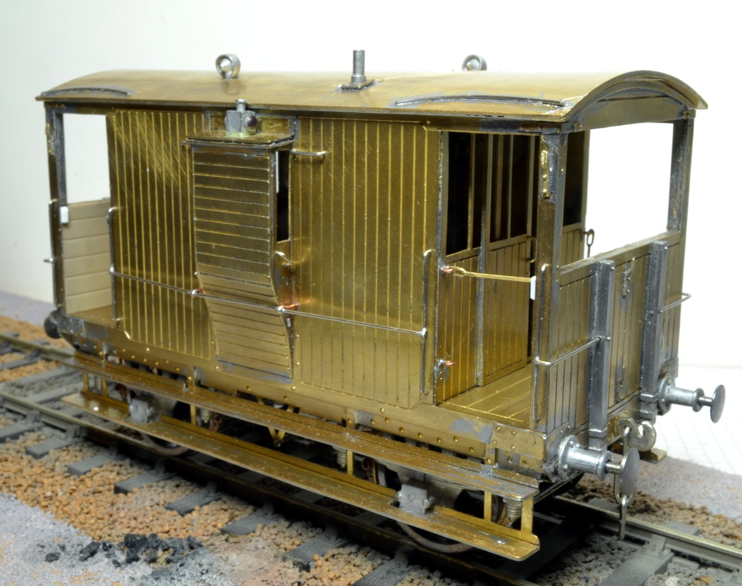
These NER goods brake vans are both from kits by Connoisseur Models, designed by Jim McGeown, and though they build well I have made a few changes and improvements to them which I detail here.
I had to hand Ian Sadler's book "NER Brake Vans" and used the photos and drawings as reference...

I removed the front panel from the centre of the topcote as I found no evidence for it.

The position of handle of the left hand side door was wrong and was changed as the doors slid only one way, towards the low end.

The end hand-rails were soldered into the sides of the vertical end baulks rather than into the front of them.

I replaced the feeble coupling hooks supplied with more chunky ones I made myself from 1.25mm nickle silver sheet.

I made a floor for the van and arranged a long screw through it to hold the roof in place.

Some metal was removed inside the topcote to add realism and an inner cross wall added which strengthens the structure.

Underneath the van I made an elbow which links the brake yokes and supports the rod to the central brake pivot.

I added a roof hand-rail on the low end though it is not soldered to the end, so the roof remains removable.

I didn't use Jim's method of springing the buffers and coupling; these are individually sprung.

4mm scale hand rail knobs were drilled 6mm and support the side hand rails.


NER V1 Brake Van from the birdcage/topcote end

Underside details are similar for both V1 and V4 vans. Note the elbow joining the brake yokes and the individually sprung buffers and coupling

Interior of V1 Brake Van with cross-wall. Much metal was removed from the top edge of the sides inside the top cote.


The photos in Sadler showed that the side lamp should be positioned on the roof of the side lookout, so the bracket supplied in the kit was dispensed with.

Inside veranda ends were made from Slaters' Plastikard planking.

I soldered metal strip to the roof edges and to the footboards to beef them up to a more realistic thickness.

Square tube was added to the veranda corners to simulate the thickness of these uprights. The door was made in the open position; this is the rear of the van where the guard figure will be positioned later. I made a pattern for an NER brake van lamp which will be produced by Invertrain next year; a trio of them will ultimately grace the rear of this van.

A floor was added and drilled for a long screw, which passes through the floor to hold the roof firmly in place.

The etched veranda safety bars are fragile and rather vulnerable so I modelled only one in place across the entrance, the others are held in their housings.

Lamp irons are from Slaters as I found the etched ones supplied just didn't work.

An etched number plate has been commissioned from Guilplates. NER lettering and numbers for the sides will be a mixture of transfers from various sources, which I hope I can make work together. 

NER V4 Brake Van. The couplings are made by myself; the buffers are independently sprung. 

NER V4 Brake Van. Note the safety bars in two positions. The lamp on top of the side lookout has been improved with a realistic red epoxy lense. 


NER V4 Brake Van from the rear/open door end. The guard figure has yet to be added to the veranda. Note the Plastikard inner planking of the front veranda. NER pattern brake van lamps will be available from Invertrain soon, to add a final flourish to the van. 

Tuesday, 19 November 2019

Highland Railway Type C brake van in action.

HR Type C goods brake van in action at CDOGG.

I think you'll agree that this photo of my HR Type C brake van in action, passing through the station, on the club layout in Carlisle is the business. It's a short train, in fact there's just an open wagon behind the engine which is HR Passenger Tank no.46. The guard can be glimpsed through the glazed rear window, he's on the other side of the van.

The ends of the van are painted red which makes for a lively colour scheme though there's no certainty that the ends were this colour when the vans came into service in 1898 as the practise of painting the ends red seems to have been phased out late in HR days.

There is little evidence of the exact colour of Highland Railway goods stock, indeed it may have varied over time and no doubt weathering changed the colour anyway. In this case, as I've modelled a van fresh from R. Y. Pickering's works, the paint is a rich red oxide with a glossy sheen. I used Precision 436 which is their Caledonian goods wagon oxide and made no changes to it.

The large H R letters flanking the ducket are HRMS Pressfix transfers; the rest of the lettering and numbers are from the water-slide sheet included with the Invertrain kit. These are carried on a varnish film, which leaves an edge, though a couple of layers of gloss over the transfer, later toned down with eggshell should disguise the edge. The transfer for the Pickering works plate is particularly effective, this is mounted on a rhomboid metal plate and trimmed with a file which nicely takes care of the varnish edge. Similarly the OIL transfer sits inside the horseshoe plate on the solebar which disguises its surround.

There are two good works photographs of the Type C van in existence which appear in Peter Tatlow's book, Highland Railway Carriages and Wagons. Apart from these the Type C van seems to have exercised a remarkable reticence towards the camera, though recently a rather grainy photo has surfaced in the HRSoc archive showing a Type C in LMS days bringing up the rear of a mineral train, headed by a Skye Bogie at Erbusaig Bay; the vans evidently saw much service on the Kyle line.


Type C van at Erbusaig Bay, approaching Kyle of Lochalsh. (HRSoc Archive)

Tuesday, 15 October 2019

Highland Railway 13Ton Type C Goods Brake Van


In a recent article in the Highland Railway Journal I mentioned that despite modellers of the Highland Railway being well served by kit manufacturers, a gap existed in the case of the Type C van. Remarkably, within weeks of publication, the gap was plugged and a sample of the kit was on my work bench. The kit was designed by Mike Williams and commissioned by Chris Smith of Invertrain.

This is a difficult kit, or you could call it a basic kit or an aid to scratch building. Whatever you call it, the kit demands patience and effort, it’s a project for the experienced modeller.

The panels have been etched into the sides and ends of the bodywork which leaves them flimsy, it may have been a better idea to have designed the sides with a separate surround to the panels, designed to be soldered on, which would have made for a more robust

body. As it is, some reinforcement and bracing is needed to produce a satisfactory structure.

I made a floor for the van and built the body and chassis as two separate modules that screw together. The chassis has a simple rigid wheelbase, without compensation.


The chassis is a separate module. Note the cross members, which support the brake hangers.


The transverse veranda locker was not part of the kit so I made one myself, which improves the appearance of the model and strengthens the structure. I double skinned both the ends and the sides of the veranda interiors, which both thickens the van walls and simplifies glazing the ends, the clear acetate sheet simply slips between the inner and outer skin. The inner end walls of the verandas are faced with 2mm Plastikard planking overlays, the side walls are not planked. The interiors of the glazed verandas are dark when the roof is in place so really you can get away with much less detail than I included, though a minimum would be to make the transverse locker and to thicken the top of the door and the opening above.


The van body is a separate module. Plasticard planking is used for the inner end walls and for the veranda floors.


There are flaws in the design which need correcting. In particular the ends of the buffer beams require shortening and an insert needs to be made to seat the ducket sides correctly. The instruction sheet, which is useful without going into minute detail, makes it clear how these improvements can be made. I used Slaters’ cast lamp irons in place of the etched offerings in the kit and also discarded the roof which was half etched and far too thin; I made a replacement from 0.45 sheet and doubled the thickness of the edges. The roof is removable, to allow glazing of the van after painting and is held in place by a screw which fits neatly down the chimney and locates into a longitudinal member in the cabin. 
There is ample scope for ingenuity in making adjustments and additions to the kit and obviously the more input and effort you put into the model, the better will be the end result


HR Type C goods brake van complete and ready for painting.

Monday, 7 October 2019

CR 15T Goods Brake Van Complete.

Caledonian Railway 15 ton brake van complete

I used Revell red enamel paint for the ends of the van. The sides and interior of the verandas were painted with a mixture of Revell 85 Orange and Precision Paints' P436, Caledonian Railway freight wagon oxide. I took note of the colour of the preserved 6-wheel CR brake van in the Museum of Scottish Railways at Bo'ness, which I thought was a bit on the orange side and mixed what I considered to be a convincing colour for the van. Transfers are Pressfix from HMRS. Though the basic colours were air brushed onto the van this was only the base colour, the finished model is the result of brush painting.

Coming Soon...

My next Blog posting will concern another goods brake van, a Highland Railway Type C 13 ton van. This is under construction at the moment from etches provided by Invertrain. It's an unusual van and an interesting build and will be available soon in kit form from Chris Smith at Invertrain Models.

Friday, 9 August 2019

Caledonian Railway 15T Goods Brake Van

CR 15 Ton Goods Brake Van construction complete
Built from Caley Coaches' etches with castings from Invertrain, the van is robustly constructed with soldered joints throughout and with a wealth of fine detail underneath which represents the brake rigging. Suspension is by means of a rocking axle which ensures a smooth ride. The tie-rods, which are out of sight behind the footboards, are connected only to the non-rocking w-irons, a loop of wire holds them in place loosely at the rocking end. The longer handrails on the sides and ends are supported midway by 4mm scale handrail knobs drilled 0.6mm to take the handrail.

Slaters' lamp irons have been used on the sides and ends of the van and will take CR pattern brake van lamps which are available from Invertrain. Note the steps mounted above the buffers and the finely detailed and fully articulated couplings which are from CPL Products, these are sprung, despite the lack of space behind the buffer beam, not really for any mechanical advantage but so that they can be removed for finishing.

The roof is held in place by a screw mounted in the chimney, in fact the chimney is the screw. Similarly, the body of the van is fastened to the chassis by two 8BA screws under the floor so the van can easily be dis-assembled for painting and glazing. The van is 120mm in length and weighs a satisfying 250g, heavy for her length, which I think helps her running characteristics.


Interior of veranda with guard, seat and brake winding mechanism.


Note the thickened inner windows and the open door to the cabin.
Ready for the paint shop.