Friday, 27 January 2017

HR Loch Cab details.

HR Loch an Dorb cab details

My previous post shows the backhead before I opened up the fire hole and added the mechanism which closed the hole. I modelled the details from photos I'd taken in the Transport Museum in Glasgow of the Loch's near relative the preserved Jones Goods. It seems that the hole was closed by a baffle which was hinged from the top and operated by that ratcheted handle on the right. A hinged grille closed onto this from the bottom though I've modelled the grille simply as a solid plate as I'm not sure how I can represent a grille in this scale.

An oil can, which I modelled on an example on display in Glasgow, is positioned to hide a joint in a pipe on the left hand splasher top where a pipe attached to the backhead meets itself as it emerges from the floor and makes its way to the splasher top rendezvous. The gap is necessary to enable the backhead to be removed.

The slight gap between the roof and the cab front will disappear when the roof is fastened in place at a later stage.


The two locating holes for the crew on the floor and splasher top are hardly visible.


I might try a coloured LED behind the fire hole to give a warm glow effect to the cab, possibly even a flicker, but I need to experiment with this, I don't know if I can make it work yet.


Friday, 20 January 2017

HR 123 Loch an Dorb; construction complete.

Though the superstructure of the Loch owes a slight debt to a Lochgorm Kits "Aid to Scratchbuilding" etch the model could be said to be almost entirely scratch built. A fair number of LGM lost wax brass castings have been used and these are easily identified on the photos following.


Showing the arrangement of the brakes and brake pull rods. I've simplified things under the tender, there was more to it than this!

The Jones Goods and the Lochs ran with identical tenders so I took some of the details of the tender front plate from the example on show in the Transport Museum in Glasgow. Note the bi-fold doors to the tender with a cut out on this side for the tablet catcher. 

Vaccum pipes always present me with a problem, here I've used n/s rod with the bend from a lost wax casting and a spring to simulate the hose.

The upright stanchions that hold the coal rails are from "T" shaped brass extrusions, coal will disguise any shortcomings in representing these fully. The bi-fold door can be seen clearly here, it needs some sort of restraint to hold it closed.

The bi-fold doors are closed, however the engine will not negotiate the curves on an average club layout with them in this position so they'll have to remain open when the engine is in action. 


The fall plate has rather large cut-outs so that the engine can negotiate curves, the bi fold door on this side is held in place by a length of chain. The cab floor is made of wooden slats from a model ship kit. 

Most of the rivets here are brass ones soldered into appropriate locating holes. The hinges of the inspection covers over the slide bars are short lengths of wire held in place with Super Glue.


Crew on the alert watching the road. The figures are available from Invertrain. At the moment the cab roof can still be removed so that the backhead can in turn be removed for painting. 


HR Loch class 4-4-0...the complete engine and tender.

A Crew for a HR Loch.

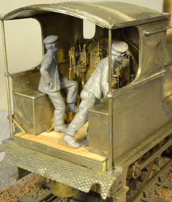
Crew seen with the roof removed

With the roof in place the cab interior is still a focus of interest and detail.


Little of the backhead detail is obscured by the crew.

Fitting figures into cabs so they don't fall over...How to do it...As construction of my HR Loch approached completion I turned my attention to providing a suitable a crew that would fit the cab without unduly obscuring the backhead detail or appearing to crowd the rather restricted cab area. You can judge for yourselves the degree to which I've succeeded. Both the figures are fixed in place with short lengths of brass rod. The driver on the left of the engine has a short 0.6mm dia. rod fixed in his bottom which locates in a corresponding hole in the splasher top. The fireman has a similar rod inserted into a hole drilled through his foot and up his left leg which locates into a hole in the cab floor. The figures are securely in place and do not fall over when the engine is in motion. I'm sure that this is the best method of fixing figures in place in cabs, they can be removed at will and the tiny locating holes are hardly visible.

Both these figures, which I designed with the cab of a 4-4-0 in mind, are now available from Invertrain