Thursday 26 December 2019

Dunrobin, Making a Start.

Dunrobin frames under construction

Lochgorm Kits' 7mm kit for Dunrobin, the duke of Sutherland's private engine, was I believe designed originally in 4mm scale by Alastair Wright of 5522 Models and enlarged to 7mm by the late Andy Copp when he took over production of the former's Highland Railway kits in 2011. Alastair began introducing Highland Railway designs to his range in the 1980's; these were hand drawn and, though not designed for 7mm, when enlarged they served well enough though they took their faults with them to the larger scale and magnified a number of these, so some of the etched parts of this kit need to be remade with more accurate replacements.

The chassis (above) is etched in sturdy 0.7 nickel silver and the frames are a respectable 26.4 mm outside diameter so I had to file a bit off the frame bushes to free the wheels. I've introduced a few more cross-members for the cylinder front and rear and for the ash pan. I've ordered an ABC Gears' Pug Special gearbox with a Canon 16 x 20 motor which I think should provide enough power for this little engine. It will sit upright in the firebox and drive the rear fixed driving axle.

Rear bogie complete

The bogie builds well without much modification and is a solid job. I used Slaters' 1/8" frame bushes for the axles. I plan to mount wiper pick-up wires behind the left hand wheels and short out the wheels on the other side; I'll try silver conducting paint and see if that works.


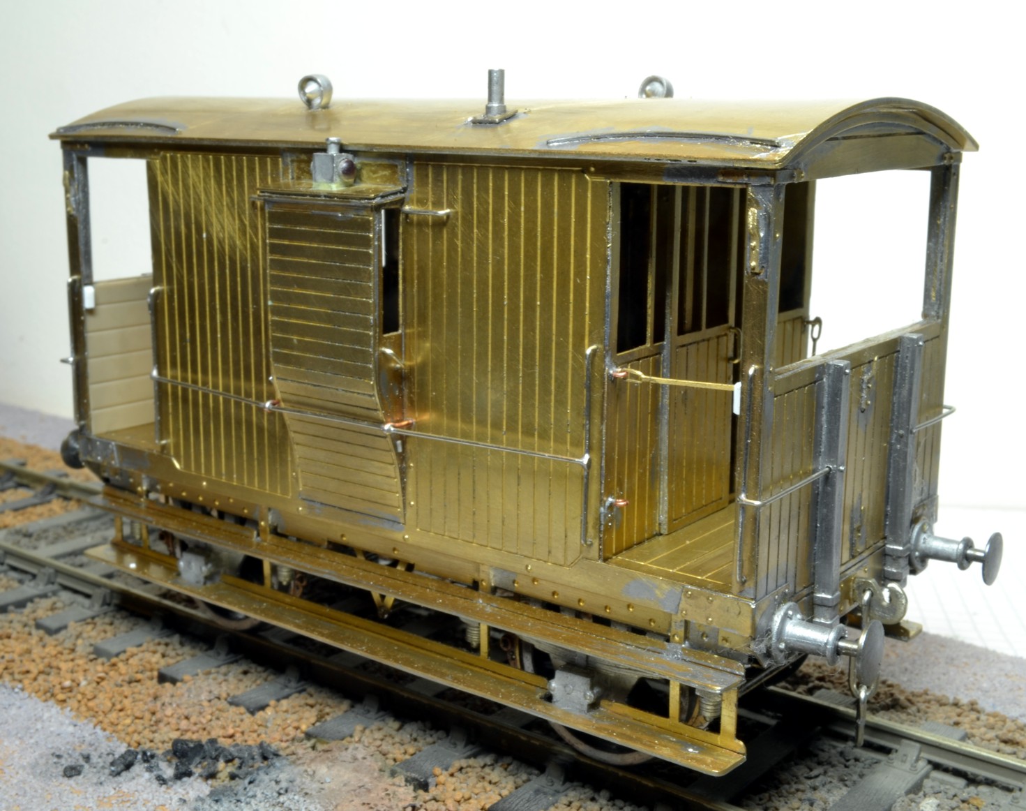
The superstructure is built on a flat wooden former. 

The boiler in the kit was half-etched to provide boiler bands, which resulted in a flimsy structure, this inadequacy when compounded with a mistake in the diameter of the boiler condemned the offending part to the recycling bin. The front splashers were found to be undersize and new parts were made to replace these too.

I intend to double-skin the cab all round so the acetate glazing will slide between the outer and inner skins; in addition the inner sliding cab windows will be constructed in this manner too. The cab front and rear present no problem though the cab sides will be replaced with more accurate parts to facilitate my ambitious glazing scheme.

Currently the real Dunrobin is undergoing major reconstruction, so there's nothing of her to see at Beamish, her home, though their newsletter is helpful and charts progress. I intend to build a detailed cab interior, though it's going to be some time before I get to this stage, I hope that by then I'll have more information on this aspect of the engine. At the moment some details, particularly of the backhead and controls, are rather hazy.

Photos taken on an Apple I-Phone 11.

Saturday 7 December 2019

Two NER Goods Brake Vans.

NER V1 Brake Van from the low end. Note the chunky couplings, position of the end hand-rails and the roof hand-rail.

These NER goods brake vans are both from kits by Connoisseur Models, designed by Jim McGeown, and though they build well I have made a few changes and improvements to them which I detail here.
I had to hand Ian Sadler's book "NER Brake Vans" and used the photos and drawings as reference...

I removed the front panel from the centre of the topcote as I found no evidence for it.

The position of handle of the left hand side door was wrong and was changed as the doors slid only one way, towards the low end.

The end hand-rails were soldered into the sides of the vertical end baulks rather than into the front of them.

I replaced the feeble coupling hooks supplied with more chunky ones I made myself from 1.25mm nickle silver sheet.

I made a floor for the van and arranged a long screw through it to hold the roof in place.

Some metal was removed inside the topcote to add realism and an inner cross wall added which strengthens the structure.

Underneath the van I made an elbow which links the brake yokes and supports the rod to the central brake pivot.

I added a roof hand-rail on the low end though it is not soldered to the end, so the roof remains removable.

I didn't use Jim's method of springing the buffers and coupling; these are individually sprung.

4mm scale hand rail knobs were drilled 6mm and support the side hand rails.


NER V1 Brake Van from the birdcage/topcote end

Underside details are similar for both V1 and V4 vans. Note the elbow joining the brake yokes and the individually sprung buffers and coupling

Interior of V1 Brake Van with cross-wall. Much metal was removed from the top edge of the sides inside the top cote.


The photos in Sadler showed that the side lamp should be positioned on the roof of the side lookout, so the bracket supplied in the kit was dispensed with.

Inside veranda ends were made from Slaters' Plastikard planking.

I soldered metal strip to the roof edges and to the footboards to beef them up to a more realistic thickness.

Square tube was added to the veranda corners to simulate the thickness of these uprights. The door was made in the open position; this is the rear of the van where the guard figure will be positioned later. I made a pattern for an NER brake van lamp which will be produced by Invertrain next year; a trio of them will ultimately grace the rear of this van.

A floor was added and drilled for a long screw, which passes through the floor to hold the roof firmly in place.

The etched veranda safety bars are fragile and rather vulnerable so I modelled only one in place across the entrance, the others are held in their housings.

Lamp irons are from Slaters as I found the etched ones supplied just didn't work.

An etched number plate has been commissioned from Guilplates. NER lettering and numbers for the sides will be a mixture of transfers from various sources, which I hope I can make work together. 

NER V4 Brake Van. The couplings are made by myself; the buffers are independently sprung. 

NER V4 Brake Van. Note the safety bars in two positions. The lamp on top of the side lookout has been improved with a realistic red epoxy lense. 


NER V4 Brake Van from the rear/open door end. The guard figure has yet to be added to the veranda. Note the Plastikard inner planking of the front veranda. NER pattern brake van lamps will be available from Invertrain soon, to add a final flourish to the van. 

Tuesday 19 November 2019

Highland Railway Type C brake van in action.

HR Type C goods brake van in action at CDOGG.

I think you'll agree that this photo of my HR Type C brake van in action, passing through the station, on the club layout in Carlisle is the business. It's a short train, in fact there's just an open wagon behind the engine which is HR Passenger Tank no.46. The guard can be glimpsed through the glazed rear window, he's on the other side of the van.

The ends of the van are painted red which makes for a lively colour scheme though there's no certainty that the ends were this colour when the vans came into service in 1898 as the practise of painting the ends red seems to have been phased out late in HR days.

There is little evidence of the exact colour of Highland Railway goods stock, indeed it may have varied over time and no doubt weathering changed the colour anyway. In this case, as I've modelled a van fresh from R. Y. Pickering's works, the paint is a rich red oxide with a glossy sheen. I used Precision 436 which is their Caledonian goods wagon oxide and made no changes to it.

The large H R letters flanking the ducket are HRMS Pressfix transfers; the rest of the lettering and numbers are from the water-slide sheet included with the Invertrain kit. These are carried on a varnish film, which leaves an edge, though a couple of layers of gloss over the transfer, later toned down with eggshell should disguise the edge. The transfer for the Pickering works plate is particularly effective, this is mounted on a rhomboid metal plate and trimmed with a file which nicely takes care of the varnish edge. Similarly the OIL transfer sits inside the horseshoe plate on the solebar which disguises its surround.

There are two good works photographs of the Type C van in existence which appear in Peter Tatlow's book, Highland Railway Carriages and Wagons. Apart from these the Type C van seems to have exercised a remarkable reticence towards the camera, though recently a rather grainy photo has surfaced in the HRSoc archive showing a Type C in LMS days bringing up the rear of a mineral train, headed by a Skye Bogie at Erbusaig Bay; the vans evidently saw much service on the Kyle line.


Type C van at Erbusaig Bay, approaching Kyle of Lochalsh. (HRSoc Archive)

Tuesday 15 October 2019

Highland Railway 13Ton Type C Goods Brake Van


In a recent article in the Highland Railway Journal I mentioned that despite modellers of the Highland Railway being well served by kit manufacturers, a gap existed in the case of the Type C van. Remarkably, within weeks of publication, the gap was plugged and a sample of the kit was on my work bench. The kit was designed by Mike Williams and commissioned by Chris Smith of Invertrain.

This is a difficult kit, or you could call it a basic kit or an aid to scratch building. Whatever you call it, the kit demands patience and effort, it’s a project for the experienced modeller.

The panels have been etched into the sides and ends of the bodywork which leaves them flimsy, it may have been a better idea to have designed the sides with a separate surround to the panels, designed to be soldered on, which would have made for a more robust

body. As it is, some reinforcement and bracing is needed to produce a satisfactory structure.

I made a floor for the van and built the body and chassis as two separate modules that screw together. The chassis has a simple rigid wheelbase, without compensation.


The chassis is a separate module. Note the cross members, which support the brake hangers.


The transverse veranda locker was not part of the kit so I made one myself, which improves the appearance of the model and strengthens the structure. I double skinned both the ends and the sides of the veranda interiors, which both thickens the van walls and simplifies glazing the ends, the clear acetate sheet simply slips between the inner and outer skin. The inner end walls of the verandas are faced with 2mm Plastikard planking overlays, the side walls are not planked. The interiors of the glazed verandas are dark when the roof is in place so really you can get away with much less detail than I included, though a minimum would be to make the transverse locker and to thicken the top of the door and the opening above.


The van body is a separate module. Plasticard planking is used for the inner end walls and for the veranda floors.


There are flaws in the design which need correcting. In particular the ends of the buffer beams require shortening and an insert needs to be made to seat the ducket sides correctly. The instruction sheet, which is useful without going into minute detail, makes it clear how these improvements can be made. I used Slaters’ cast lamp irons in place of the etched offerings in the kit and also discarded the roof which was half etched and far too thin; I made a replacement from 0.45 sheet and doubled the thickness of the edges. The roof is removable, to allow glazing of the van after painting and is held in place by a screw which fits neatly down the chimney and locates into a longitudinal member in the cabin. 
There is ample scope for ingenuity in making adjustments and additions to the kit and obviously the more input and effort you put into the model, the better will be the end result


HR Type C goods brake van complete and ready for painting.

Monday 7 October 2019

CR 15T Goods Brake Van Complete.

Caledonian Railway 15 ton brake van complete

I used Revell red enamel paint for the ends of the van. The sides and interior of the verandas were painted with a mixture of Revell 85 Orange and Precision Paints' P436, Caledonian Railway freight wagon oxide. I took note of the colour of the preserved 6-wheel CR brake van in the Museum of Scottish Railways at Bo'ness, which I thought was a bit on the orange side and mixed what I considered to be a convincing colour for the van. Transfers are Pressfix from HMRS. Though the basic colours were air brushed onto the van this was only the base colour, the finished model is the result of brush painting.

Coming Soon...

My next Blog posting will concern another goods brake van, a Highland Railway Type C 13 ton van. This is under construction at the moment from etches provided by Invertrain. It's an unusual van and an interesting build and will be available soon in kit form from Chris Smith at Invertrain Models.

Friday 9 August 2019

Caledonian Railway 15T Goods Brake Van

CR 15 Ton Goods Brake Van construction complete
Built from Caley Coaches' etches with castings from Invertrain, the van is robustly constructed with soldered joints throughout and with a wealth of fine detail underneath which represents the brake rigging. Suspension is by means of a rocking axle which ensures a smooth ride. The tie-rods, which are out of sight behind the footboards, are connected only to the non-rocking w-irons, a loop of wire holds them in place loosely at the rocking end. The longer handrails on the sides and ends are supported midway by 4mm scale handrail knobs drilled 0.6mm to take the handrail.

Slaters' lamp irons have been used on the sides and ends of the van and will take CR pattern brake van lamps which are available from Invertrain. Note the steps mounted above the buffers and the finely detailed and fully articulated couplings which are from CPL Products, these are sprung, despite the lack of space behind the buffer beam, not really for any mechanical advantage but so that they can be removed for finishing.

The roof is held in place by a screw mounted in the chimney, in fact the chimney is the screw. Similarly, the body of the van is fastened to the chassis by two 8BA screws under the floor so the van can easily be dis-assembled for painting and glazing. The van is 120mm in length and weighs a satisfying 250g, heavy for her length, which I think helps her running characteristics.


Interior of veranda with guard, seat and brake winding mechanism.


Note the thickened inner windows and the open door to the cabin.
Ready for the paint shop.

Wednesday 5 June 2019

Highland Railway Type B goods brake van completed.

Highland Railway Type B goods brake van c. 1899.

Pictorial evidence for the livery of the Type B van is elusive and mostly to be derived from the well known photo of HR 23 at Perth in about 1904. Part of the van can be glimpsed in the background beyond the engine. The position of the insignia on the van side is clear and I have positioned the initials HR with 53 below accordingly on the model. The photo shows part of the word BRAKE centrally on the right hand panel, so GOODS must have appeared on the left hand panel. It seems probable that this particular van had no beading in the middle of the outer panels as this would have disrupted the lettering. A photo of part of Type B van no.47 in Highland Railway Album clearly shows a central bead to the end panel, the model similarly has a central panel bead so the lettering has been located between this and the door. between 1902/3 and 1912 records tell us that van roofs were mid grey, prior to this and later vans were turned out with white roofs though this must have discoloured quickly.

A name board for the name of the guard and the home station is located low down on the left of the van. The only description of the colour of Highland Railway brake vans at this time I've come across is that they were "rich red oxide", they may have had vermillion ends in their early days too though this is not certain, nevertheless I've painted the ends of the model red. I used Precision Paints' P436 Caledonian Railway freight wagon oxide for the van sides and lightly weathered the van with an airbrush.

The current Highland Railway Journal for Spring 2019 carries an article on the construction of this model which a second follow-up article in the next Journal will conclude. 

Friday 26 April 2019

Highland Railway Type B goods brake van.


Highland Railway Type B goods brake van d.25

I was aware that Walsworth Models had produced a kit for this attractive 6-wheel van and when I saw it on the Highland Railway stand at MRS earlier this year I thought it looked a quality product and I bought one. The kit proved to be well designed and etched in modeller friendly nickle silver, though rather let down by the quality of the brass castings.

I made several changes as I built the van, perhaps the most radical was altering the curve of the van roof which I thought was too flat. To do this I soldered a new correctly curved top onto the van ends, it wasn't a lot different but it made all the difference and I felt it looked better. However this small alteration had the unforeseen knock-on effect of having to remake the roof lookout windows, front and back, to match the curve of the roof and this was not a small job. I cut them to shape using a  pattern that I made from Peter Tatlow's very credible drawing on page 180 of his "Highland Railway Carriages and Wagons". I noticed that the windows on the drawing were a little different to those supplied in the kit so remaking them proved to be a definite improvement to the model.

I thought that the way the kit was designed left the edges of the windows very thin, about 0.25mm which is less than half an inch, so I soldered 0.45 n/s sheet behind all the window openings, lookout, doors and van ends, so the glazing would now be set in over an inch and give the van a more chunky feel. I also beefed up the rather slim footboards with a lamination of 0.25 strip and cut down the upper footboard to allow room for horse hooks on the solebars.

The axle boxes and springs were cast as one piece in brass, the use of this material being I suppose an attempt to upgrade the quality of the kit. However something had gone awry at the casting stage and the axle boxes were set at an awkward angle to the springs and there was nothing I could do to fix the error other than cut the offending axle box off and discard it. The springs by themselves were acceptable and I soldered them to the solebar without the brass axleboxes which I replaced with some nicely cast white metal ones I had in hand from a Lochgorm kit.

The couplings and safety chains that enliven the buffer beam I made myself; the safety chain hooks came from the spares box as those on the etched sheet were over-etched out of existence. The coupling hooks are sprung fairly stiffly, largely to facilitate removal when I paint the model. I don't want the springs to allow the coupling hooks much movement if any.

The improvements I made to the van are small though the effort in making them was huge, I think it was time well spent though you can judge for yourselves by clicking on the photos to enlarge them.   


The suspension system and brake gear.


The two near axles are mounted on a centrally pivoted bogie, the rear axle is screwed to the floor; a long 0.6mm rod runs the length of the floor and acts as a self centering spring on the bogie. Unseen are the screws that hold the superstructure to the underframe to allow access to the interior for glazing at a later stage.

So watch this space... I'll be working the van to a finish now; tomorrow the etch primer then the paint shop as I need to photograph the painted model in time to make the deadline for the Highland Railway Journal.

Friday 22 March 2019

Merrie Carlisle, more progress

LMS 5050, Merrie Carlisle

When we observe a real steam engine the viewpoint is usually low, however in the case of a model it's quite different, we view the model from above and one of the first things we notice is the space under the boiler between the frames where the inside motion sits and a Precedent displays her inside motion quite prominently. At the moment Merrie Carlisle has no inside motion, a very noticeable omission which needs to be remedied. I'm working on it and if I can make the motion work then I will, if not then it'll have to be simply cosmetic motion, non-working that is, either way it'll fill the gap.


The crew's working space...

I'm working on the loco crew now, they need to be designed so they don't both stand in the cab which is a very restricted area and even more so since the splashers are closer together than on the real engine, it's tighter by about a scale 5 or 6 inches, so watch this space...


The cab and backhead in detail.

The pale green floor area is Milliput into which a brass fret had been pressed to simulate the small wooden blocks that formed the lower cab floor on these engines, it'll work better when it's glued down and painted. There are two wooden inserts in the upper cab floor which have been made out of planking from a model ship kit. Most of the backhead detail owes something to castings from LGM. I think I've included everything you can see on the real thing though I never found room for the blower handle which I think was in the right hand corner somewhere.

Friday 1 March 2019

LMS 5050 Merrie Carlisle progressing

The triangular ash hopper has a shield to prevent ash blowing up into the motion, the hole in it is not prototypical, it is for access to the body fixing screw.

The cylinder drain cocks can be seen below the front cylinder covers, their operating rods have been modelled as far as possible. The join between the working frames and the wider forward extension of the frames, which are fixed to the footplate, is clearly seen though is not obvious when the wheels are in place. The gap between the front and rear plates of both the buffer beam and the ash hopper are filled with Milliput. The void in the buffer beam allows the front coupling, which is pegged in place,  to be removed; these are fully working couplings supplied as a kit by CPL Products, the characteristic LNWR "T" bar is an added refinement. Note the front sand box nestling behind its outer cover, the lower part of the sand pipe is yet to be fitted.


Work on the detail in the cab is at an advanced stage.

 
The roof is soldered to the inner spectacle plate, both this assembly and the backhead can be removed so I can work on the detail, some of which you can see in this view of the engine. The lower footplate of the real engine consisted of a casting which accommodated wooden blocks a fraction over 1" square. I've not modelled this feature yet as I need some Scale Link 1mm square mesh which is proving difficult to come by. The idea is to push the mesh onto a flat piece of Milliput which, hopefully, will pop up through the mesh to form the "wooden" blocks!


Cab details progressing though there's still more to add.

 
Most of the castings used in the cab are from Laurie Griffin Miniatures and though they have all been modified in some way without them this sort of detail would not be possible.


Superstructure and frames pose on the wooden block that the engine is built on surrounded by the debris of a working session in the studio.


I bought some collarless handrail knobs from 62C Models which hold the handrail that runs along the larger vacuum ejector pipe on both sides of the engine. On the right hand side the hand rail operates the blower valve which is attached to the smokebox, this was done by turning a handle in the cab which I have not yet managed to model. Behind the chimney sits the smokebox regulator lubricator for which I have not been able to locate a suitable casting so I'll have to make one myself. The LNWR Society's re-publication of Bill Finch's book on building an LNWR Jumbo is invaluable and provides drawings of most of the details I've included in the model or have yet to make, Jack Nelson's book "LNWR Portrayed" is also useful to modelers

Friday 25 January 2019

Merrie Carlisle Progress...

An incomplete Merrie Carlisle had a test run on the club layout in Carlisle recently, she went well and was well received by the members.


The smokebox has yet to be soldered into place and at this stage the wrapper has no rivet detail, nor do the cab side sheets. I plan to add the rivets later when construction is complete and I've done some research into the possibilities, of which there are four...

1. Brass rivets soldered or glued into appropriate holes. The rivets heads on the real engine are 3/4" d. which in 1:43 scale is 0.435mm. I think 0.5 would be near enough, though I'm sure drilling 250 rivet holes would be a task expensive in small drills.

2. HGW cast resin transfer rivets seemed a good idea and indeed they are very effective, easy to work with and leave no backing on the model as this is peeled away after the transfer sets. Unfortunately they're too small for gauge O locomotives as they're designed for model aircraft, 0.25 is the largest diameter of rivet they make and though they're fine for aircraft, to us they're mere pimples.

3. Archer Surface Detail transfer rivets are the favourite at the moment, they make O gauge rivets about the right size which adhere well to the primer coat. I've experimented and rubbed them with my finger and they stay put. They stand proud of the surface of the model by 0.12mm which is nearly 1/4" and a little on the low side compared to a brass rivet. I'll have to try them and see how convincing they are, this is after all an experiment. Another reservation I have is that the resin rivets are carried on a carrier film though this is very thin and I think will disappear under the paint.

4. Small Shop produce a "Nutter" tool which makes rivet and nuts and bolt heads that are glued in place with varnish. I've only seen a video of this in action but on the face of it the tool looks like a viable though rather expensive proposition.


The wheels are insulated at the rim and and are cast and turned to size by JPL Models.


The motor is restrained by a vertical member which engages in a hole in the top of the motor.
I may replace the M1824 with a more powerful M1833 if the locomotive proves underpowered, I think there's probably room for one.

The front wheels are sprung individually, following Geoff Holt's example, this arrangement is just visible bottom right.


There is a very visible void beneath the boiler so inside motion will have to be fitted, though I don't know whether I can make it work.


The upper part of the motion plate is in place between the upper part of the frames, which are attached to the footplate. The lower part of the motion plate will be attached to the working frames below and will carry the slide bars and provide support for the valve rods. The LNWR Precedents were fitted with Alexander Allan's straight link valve gear, mine will be fitted with the nearest to that ideal that I can manage.


The brass backhead casting is from LGM and has been narrowed at the sides because of the intrusion of the wider than scale cab splashers in O gauge fine scale. Recesses in the upper floor are for wooden inserts. There's a wealth of detail to go in the cab, it's a busy place. 

Electrical pick-up is by the so called American system, the current is led from the tender to the motor through the drawbar, which is insulated from the engine, using a method described by Nick Baines. I've attached a pick-up wire to the drawbar at the tender end which bears on the bottom of the tender floor above to ensure a good contact. Without this addition contact with the tender was uncertain and resulted in uneven running.


There's only a 9" gap between buffer beam and smokebox front so it's a tight fit for the cylinder lubricators which were modified for this situation from LGM castings.