Showing posts with label 62c Models. Show all posts

Monday, 17 April 2023

HR 8-ton double-deck sheep van with planked sides in 7mm scale.


Pete's new addition to his range of aids to scratch-building provides resin sides and ends for a Highland Railway 8-ton double-deck sheep wagon d.17. Parts from the trade, such as the W-irons, buffers, springs, axle boxes and couplings are easily sourced (see below). Additional items such as brake gear, roof and internal floors can be cut from sheet metal or Plastikard, so in a round-about way a multi-media kit is assembled to each individual modeller's choice. 

Price is £22.50 plus postage at cost £1.60 1st Class or £1.15 2nd Class.
Buy 2 or more and postage is Free.

Contact Pete on...
armstrongps1@gmx.com
017687 71302
07342 617 813

This is what you get...


The openings are filled with a thin membrane. Hold to the light to identify the openings and push out the membrane with the back of a scalpel blade, it only takes a few minutes. The resin ingates (with holes in) are cut off with a fine coping saw and the bottom of the castings filed flat. 

In addition you'll need...

Slater's 3' 1" wagon wheels ref: 7120
Slater's 1mm Plastikard, 7mm planking and 1.5mm strip for battens.
W-irons from Slater's or The Highland Railway Society.
Springs, axle-boxes and buffers from Invertrain.
Couplings from CPL Products.
Horse hooks, brake lever guard and collarless hand rail knobs from 62C Models.


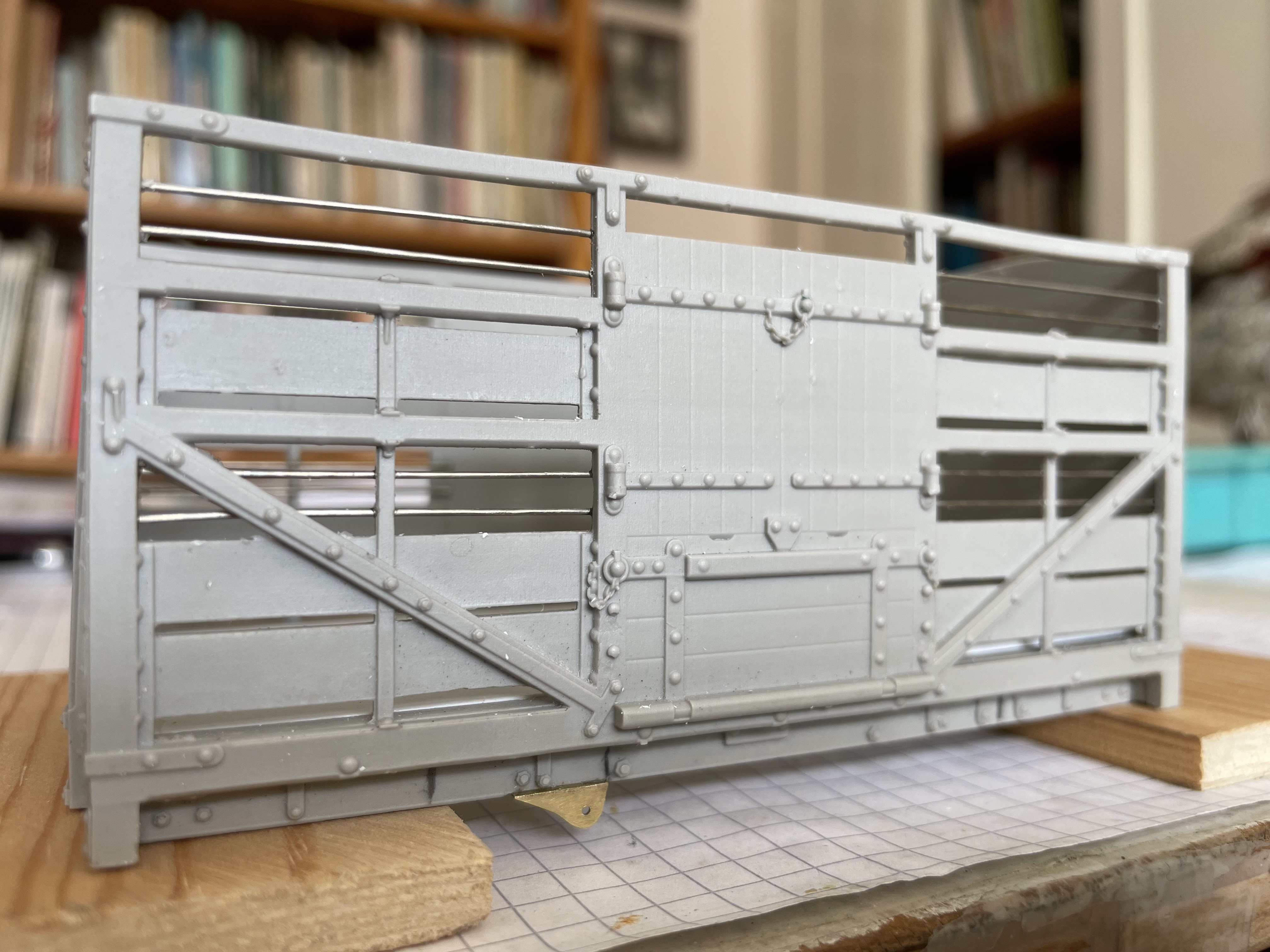
Close up showing the fine detail of the resin castings after the openings have been cleared of membrane. Horizontal bars are made from 0.6 nickle silver or brass wire glued into slots behind the openings.


The upper floor sits behind the horizontal midway strut and serves to brace the structure. The roof is made from 0.4mm nickle silver sheet, rolled to shape; Plastikard would provide an alternative solution.    

 Plastikard planking, with 1.5mm battens to provide a footing for livestock, overlays the 1mm thick lower floor. Note the interior detail and the horizontal wire glued in slots across the openings. The ends of the planks marked with an X have been trimmed slightly to seat the end.

View of the rocking-axle, coupling and buffer shanks, which run in slots behind the solebars. The floor under the axles has been built up 1.5mm with Plastikard sheet to provide the correct ride height.

The upper deck of the van is split in half along its length to allow it to seat in place; an overlay of battened Plastikard planking sits on top of this. The planked floors show up well in good light, even with the roof in place and are worth the effort of detailing them with battens.

 An additional, though optional detail, is the chain which holds the pin which locates in the holes in the rack to hold the brake lever down. 

Brake shoe and brake lever are fabricated from nickel silver sheet. Springs and axle-box are cast in white metal from my own master patterns in my workshop.
 
 
The sides and ends are glued together and 0.6 n/s wire is fastened behind the opening in slots provided; which may need enlarging a little. The ends of the horizontal planks need trimming slightly inside, to allow the sides to seat in place.


A short length of square section tube has been fashioned to make the brake lever hanger, this is glued into a shallow slot cut in the sole-bar.


The horizontal handrail is held in place by collarless handrail knobs which locate into holes in the uprights. The handrail is soldered to the knobs in situ then the assembly is removed, the wire bent to fit the outer holes and replaced.


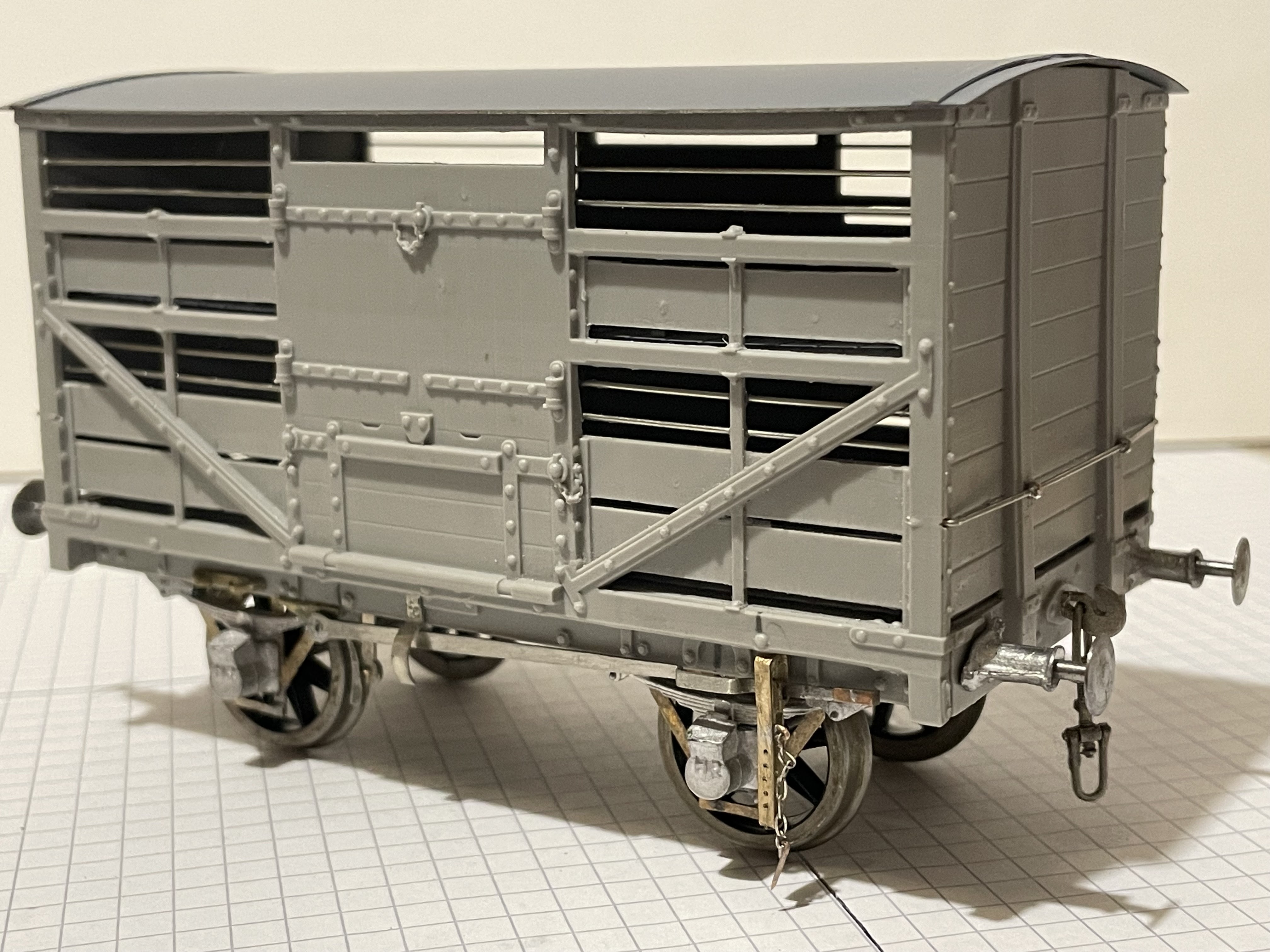
The van is weighted up to 150g and runs superbly. Note the brake lever guard set just off-center on the sole-bar. There doesn't seem to be much room for a cast number plate on the narrow sole-bar, perhaps sheep vans made do with numbers painted on the lower horizontal boards.  


Friday, 1 March 2019

LMS 5050 Merrie Carlisle progressing

The triangular ash hopper has a shield to prevent ash blowing up into the motion, the hole in it is not prototypical, it is for access to the body fixing screw.

The cylinder drain cocks can be seen below the front cylinder covers, their operating rods have been modelled as far as possible. The join between the working frames and the wider forward extension of the frames, which are fixed to the footplate, is clearly seen though is not obvious when the wheels are in place. The gap between the front and rear plates of both the buffer beam and the ash hopper are filled with Milliput. The void in the buffer beam allows the front coupling, which is pegged in place,  to be removed; these are fully working couplings supplied as a kit by CPL Products, the characteristic LNWR "T" bar is an added refinement. Note the front sand box nestling behind its outer cover, the lower part of the sand pipe is yet to be fitted.


Work on the detail in the cab is at an advanced stage.

 
The roof is soldered to the inner spectacle plate, both this assembly and the backhead can be removed so I can work on the detail, some of which you can see in this view of the engine. The lower footplate of the real engine consisted of a casting which accommodated wooden blocks a fraction over 1" square. I've not modelled this feature yet as I need some Scale Link 1mm square mesh which is proving difficult to come by. The idea is to push the mesh onto a flat piece of Milliput which, hopefully, will pop up through the mesh to form the "wooden" blocks!


Cab details progressing though there's still more to add.

 
Most of the castings used in the cab are from Laurie Griffin Miniatures and though they have all been modified in some way without them this sort of detail would not be possible.


Superstructure and frames pose on the wooden block that the engine is built on surrounded by the debris of a working session in the studio.


I bought some collarless handrail knobs from 62C Models which hold the handrail that runs along the larger vacuum ejector pipe on both sides of the engine. On the right hand side the hand rail operates the blower valve which is attached to the smokebox, this was done by turning a handle in the cab which I have not yet managed to model. Behind the chimney sits the smokebox regulator lubricator for which I have not been able to locate a suitable casting so I'll have to make one myself. The LNWR Society's re-publication of Bill Finch's book on building an LNWR Jumbo is invaluable and provides drawings of most of the details I've included in the model or have yet to make, Jack Nelson's book "LNWR Portrayed" is also useful to modelers

Tuesday, 4 July 2017

HR Passenger Tank backhead and cab interior.

HR46 Backhead complete.

I based the Drummond Passenger Tank backhead, to some extent, on that of the HR Loch class engines, for which a GA drawing exists. My presumption is that the Loch backhead followed standard Highland practice, so in taking this as my example I should be working on the right lines. I also took note of the backhead of the preserved Caledonian Railway 0-4-4T which my wife photographed from inside the cab. I thought that a Scottish engine, similar in many respects to the Passenger Tank, might afford some insight into the mysterious world of backheads c.1900.

The castings used in my reconstruction were mostly from LGM though I found the castings on offer from 62C Models useful too and of good quality, the injectors being from that source. Most of the castings I used were reduced in size and remodelled to some extent to suit the miniscule backhead. As an example, the bottom parts of the water gauge castings were cut off and replaced by a small tap, made from a hand rail knob and a length of fine wire, which reduced their length and enabled me to fit them above the shelf over the firedoor, which I reduced in width to leave room for the firedoor opening lever which is on the right, you can see its handle just below the water gauge.

On the left hand side of the spectacle plate can be seen the driver's brake valve which is connected to the injector on that side by a "flexible" connection. In reality the two are not connected at all, the flexible hose only butts against its continuation in the dark corner of the cab to enable the inner spectacle plate and backhead assembly to slide upwards for removal. There is an inner and outer spectacle plate, which much simplifies glazing at a later stage.
There is a metal plate on the cab floor under the firehole which is a detail I took from the preserved Caledonian engine, the floor planking, which is flush with the metal plate, is made of stripwood from a model ship kit.
The handle of the token exchange apparatus, which is out of sight outside the cab, protrudes into the cab behind the cab door stanchion.
The reversing lever, which attaches to the inside of the left hand inner tank, was a mini construction project in its own right. The tanks flank the backhead on either side of the cab and detract from the already restricted area of the cab, leaving little space in the model available for an engine crew ( see my previous post for a solution to the crew problem).

Tuesday, 6 June 2017

HR Passenger Tank... more progress.

HR 46 Superstructure practically complete.

The superstructure is almost complete and detail work is well under way. Castings for the tank top water fillers need a little modification and the dome needs rather more drastic surgery as I had to remodel the (wonky) safety valves which are mounted on top of them.
The smokebox door is made from 0.45mm nickle silver sheet cut to shape and persuaded into a convex shape in a doming block after which much filing produced the result above.


Cab interior partially finished


Some of the cab and backhead fittings are in place in this view, most of the castings have been sourced from LGM and need modifying for best effect. On the left cab side wall is the driver's brake valve that I cut down to size and at the same time moved the handle to the nearside, this apparatus will have a pipe that connects with the left hand injector which has yet to arrive though I've ordered what looks like an appropriate pair from 62C Models. Fastened to the the right of the spectacle plate is a lubricator again cut down from an LGM casting to a more reasonable size. The backhead water gauges look too big and need reducing in length, I may cut them down and add a small tap to the bottom which might leave room for me to fit a firebox door handle. The handle for the tablet catcher can be seen protruding into the cab between the stanchion and the inner side tank.


Opening door with cut-out to accommodate the tablet catcher mechanism. 


The hinged door has a sneck which fastens behind the front cab stanchion to keep the door closed. Inside the cab can be seen the coal hole door which opens by sliding upwards : beyond is the brake stanchion.


HR 46 Crew in action poses.


The driver is from the "Heroes of the Footplate" range which is now available from Chris Smith at "Invertrain". The fireman is my first essay in producing a shovelling figure, moulds for this are currently under development. Adding figures to the cab points up the very restricted space in which crews worked in these little engines.