Showing posts with label LMS 5050. Show all posts

Monday, 5 February 2024

LNWR Precedent...Merrie Carlisle


Renewed Precedent Class, Merrie Carlisle, LMS 5050 in 7mm scale 

The engine is built in nickle-silver, without the aid of a kit, though the tender is a Gladiator Models product, to which I made a few improvements. It is intended to finish the model in early LMS red, Merrie Carlisle being one of only four of this class to be turned out in full red passenger livery. When the engine first appeared in its new livery it carried number 5050 on a smokebox plate and retained its original socket lamp-irons. The Bill Finch Portfolio of Locomotive Details, published by the LNWR Society was an invaluable help in building the model. The only kit I know of for a Precedent is a Mercian Models product, which may no longer be in production.

Precedent chassis and mechanism revealed

Power is provided by an M1824 motor and ABC gearbox, mounted on the front driver and fitted with an MSC flywheel. I could have fitted a more powerful M1833, though there would not have been room for a flywheel. I prefer the smaller motor/flywheel set-up, which greatly enhances the engine's running qualities. Pick-ups are phosphor-bronze wire wipers on the left-hand wheels; the right-hand wheels are shorted by hidden wires. The front carrying wheels are from Slater's, who do not produce suitable Precedent driving wheels, those I used were supplied by JPL and may not be available now. 


Allan's straight link motion, simplified by the omission of the drop-links, fills the gap under the boiler. The valve rods pass through a gap in the motion plate. The sand boxes, which flank the motion plate, are filled with yellow Milliput.


The inside motion unit removed.

The tool box castings have been detailed and display how they were fastened to the tender top. 

Under the tender.

The water pick-up apparatus has not been included under the tender though the double brake pull-rods have been modelled fully. Note the tender buffers, which really work, being sprung behind the buffer beam. 

The Crew.


The loco crew are from my own sculpture and are cast in white metal in my workshop. Both figures are mounted on thin sheet metal bases and secured to the deck with double-sided tape. The fireman stands on the tender fall-plate, his base is made from scrap chequer-plate. The poses of the crew are designed so they relate to both the engine and to each other. They were designed as the model progressed and are an integral part of the model, by no means merely an afterthought.


The brakes are a tight fit.

A busy cab interior.


I built the cab interior with the help of castings from Laurie Griffin's range, most of which were modified in some way to suit a Precedent. I used Bill Finch's drawings for reference and don't think I left anything out. The roof, which is attached to the inner skin of the spectacle-plate, can be lifted off, which allows the back-head to be removed too. The spectacle-plate is double-skinned so the window glazing simply slips between the inner and outer skins. The prominent reversing wheel would have been better as a nickle-silver casting to approximate the steel original, but I could only get a brass one, I'm sure it'll look fine with the rim buffed up.

I heard recently that the "Master" himself, James Beeson, painted his reversing wheels red!


Friday, 22 March 2019

Merrie Carlisle, more progress

LMS 5050, Merrie Carlisle

When we observe a real steam engine the viewpoint is usually low, however in the case of a model it's quite different, we view the model from above and one of the first things we notice is the space under the boiler between the frames where the inside motion sits and a Precedent displays her inside motion quite prominently. At the moment Merrie Carlisle has no inside motion, a very noticeable omission which needs to be remedied. I'm working on it and if I can make the motion work then I will, if not then it'll have to be simply cosmetic motion, non-working that is, either way it'll fill the gap.


The crew's working space...

I'm working on the loco crew now, they need to be designed so they don't both stand in the cab which is a very restricted area and even more so since the splashers are closer together than on the real engine, it's tighter by about a scale 5 or 6 inches, so watch this space...


The cab and backhead in detail.

The pale green floor area is Milliput into which a brass fret had been pressed to simulate the small wooden blocks that formed the lower cab floor on these engines, it'll work better when it's glued down and painted. There are two wooden inserts in the upper cab floor which have been made out of planking from a model ship kit. Most of the backhead detail owes something to castings from LGM. I think I've included everything you can see on the real thing though I never found room for the blower handle which I think was in the right hand corner somewhere.

Friday, 1 March 2019

LMS 5050 Merrie Carlisle progressing

The triangular ash hopper has a shield to prevent ash blowing up into the motion, the hole in it is not prototypical, it is for access to the body fixing screw.

The cylinder drain cocks can be seen below the front cylinder covers, their operating rods have been modelled as far as possible. The join between the working frames and the wider forward extension of the frames, which are fixed to the footplate, is clearly seen though is not obvious when the wheels are in place. The gap between the front and rear plates of both the buffer beam and the ash hopper are filled with Milliput. The void in the buffer beam allows the front coupling, which is pegged in place,  to be removed; these are fully working couplings supplied as a kit by CPL Products, the characteristic LNWR "T" bar is an added refinement. Note the front sand box nestling behind its outer cover, the lower part of the sand pipe is yet to be fitted.


Work on the detail in the cab is at an advanced stage.

 
The roof is soldered to the inner spectacle plate, both this assembly and the backhead can be removed so I can work on the detail, some of which you can see in this view of the engine. The lower footplate of the real engine consisted of a casting which accommodated wooden blocks a fraction over 1" square. I've not modelled this feature yet as I need some Scale Link 1mm square mesh which is proving difficult to come by. The idea is to push the mesh onto a flat piece of Milliput which, hopefully, will pop up through the mesh to form the "wooden" blocks!


Cab details progressing though there's still more to add.

 
Most of the castings used in the cab are from Laurie Griffin Miniatures and though they have all been modified in some way without them this sort of detail would not be possible.


Superstructure and frames pose on the wooden block that the engine is built on surrounded by the debris of a working session in the studio.


I bought some collarless handrail knobs from 62C Models which hold the handrail that runs along the larger vacuum ejector pipe on both sides of the engine. On the right hand side the hand rail operates the blower valve which is attached to the smokebox, this was done by turning a handle in the cab which I have not yet managed to model. Behind the chimney sits the smokebox regulator lubricator for which I have not been able to locate a suitable casting so I'll have to make one myself. The LNWR Society's re-publication of Bill Finch's book on building an LNWR Jumbo is invaluable and provides drawings of most of the details I've included in the model or have yet to make, Jack Nelson's book "LNWR Portrayed" is also useful to modelers

Saturday, 29 December 2018

Merrie Carlisle...first moves.

King Arthur lives in Merrie Carlisle,
And seemly is to see
And there with him Queen Guinever
That bride so bright of blee 

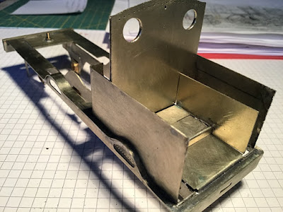
When I mentioned recently that I intended to make a start on a model of the LNWR's "Merrie Carlisle", one of the club members at CDOGG remarked that a plain engine such as a Precedent should provide few problems, well I beg to differ, it's just one problem after another. Of course that's probably because it's a scratch built engine and as such it's a prototype and I'm running into all the problems and unforeseen snags that are bound to crop up building any prototype. So it has been slow going, a tale of trial and error and of two steps forward and one step back! Nevertheless, as the accompanying pictures show I have the beginings of a Precedent taking shape in the studio. There are no correct Slaters' wheels available for this engine, which I mentioned to their technical department, however my revelation was met with a decided lack of interest. So I sourced the wheels from JPL Models and I have them in hand now, they are cast iron and nicely turned to size though demanding a good deal of work on the spokes to finish them. My drawing of the engine shows 6ft 9"wheels, those made for me by JPL are, at my insistence, 6ft 6" across the treads, though they measure 7ft across the flanges; I hope that the splashers will house the wheels without having to be made oversize. The boiler will have to be cut away to allow the front driving wheels clearance, a necessary compromise when working in gauge O fine scale and a reminder that this is a model, not the real thing.

There is a kit available for an LNWR Precedent from Mercian Models (ref. LNW1 @ £250 ) which is based on the old Modeller's World kit, however I chose the scratch building route as I thought it probably less bothersome and a good idea to put the saving into some quality brass castings.


"Merrie Carlisle" was built at the LNWR's Crewe Works in 1894 as number 860 and took its name from the opening line of a fifteenth century poem, "The marriage of Sir Gawain". It was one of only four Precedents turned out in the LMS red livery after the grouping and at the moment it is in that guise as LMS 5050 that I intend to finish the engine.


Note the double skinned cab spectacle plate. Rivets are absent from the cab sides though I intend to add them from Archers' Surface Detail resin transfers at a later stage.

Frames are cut from 0.7 nickle silver and are a respectable 27mm wide. The troublesome curly footplate is from 0.4 n/s.
Cab floor in place with locations for square wooden inserts on the upper level. The distance between splashers on the real engine is a miserly 4ft 3". The model splashers are only 3ft 10" apart, leaving even less working space for the crew.

Slaters' brass hornblocks slide in slots in the 0.7mm frames and are held in place by an "L" shaped keeper plate.  

The frames stop short of the open footplate behind the buffer beam. The wider cosmetic front frames are attached to the footplate and overlap the working frames in an obvious manner though when the wheels are in place the join is hardly noticeable.