Monday, 28 October 2024

HR Loco crew in 7mm scale.


HR NEW SERIES. Driver HR1 and Fireman HR2


 Loco crew have always been a favorite modelling subject of mine and I've recently sculpted some new ones in 1:43 scale based on photos of Highland Railway loco crew, which are now available to enliven the cabs of your locos. There are currently four New Series figures which can be seen in the accompanying pictures. These are cast in quality white metal and are available assembled and mounted on a small base unpainted.

A limited number of figures, painted by myself, are available while stocks last, these are illustrated in the accompanying photos.

Prices.

Painted Figures are £15. You can mix and match any of the painted figures seen in the pictures.


NEW SERIES 

HR1 Driver, HR2 Fireman, HR3 Guard, HR4 Fireman Tank Engine.

New Series are unpainted assembled figures @ £8

Postage @cost

Email. armstrongps1@gmx.com


Three locomotive drivers

Four locomotive firemen

A driver and fireman that go well together.

Assembled unpainted white metal figures. NEW SERIES HR3, HR1 and HR2 

Designed for a tank engine, this is NEW SERIES HR4

Friday, 25 October 2024

HR 118 In action.

HR118A glides smoothly through the complex point-work on the CDOGG club layout. The wagon behind the engine is a HR fish truck, built from my own Sides and Ends resin castings and still available.


HR118A had its first outing on the club layout in Carlisle last week and performed well with a train of ten pre-grouping wagons and a guards van, which though less than it could have hauled, was a realistic load, as the prototype engine was not noted for its pulling-power. The engine is painted in Cumming's unlined moss green livery with vermillion buffer beams, the front one carrying the number 118A in the Highland's distinctive gold lettering edged with green and black. Cumming introduced this livery in 1923 and photographic evidence shows the engine in this livery during its later days of service on the Highland. There are currently no Highland Railway colours in production, so I was fortunate to acquire a practically unused tin of Phoenix moss green from an HRSoc member (P728 HR Dark Green 1912-1922) which saved me the problem of trying to mix this elusive colour myself. I used an old sheet of Guilplates Loco Insignia transfers which, being Methfix, have no hard to disguise carrier film and make for a neat job, particularly on the tank sides. The loco crew are my own recent sculpture, cast in white metal and designed to maximise the space available in the cab of a small locomotive. The loco lamps are also my own castings, they add a touch of colour, which together with the brightwork, the gold shaded insignia and vermillion buffer beams enliven the somber livery.


The driver is on the right, positioned in the doorway where he doesn't crowd the cab.

The fireman is on the left, he leans out, looking ahead and allows an unobstructed view of the busy cab interior. 

Tuesday, 30 July 2024

A New Photo of HR 118

 Image of 118 cropped from a photo of  a Scrap Tank at Inverness.

I was unaware of the image above until it was brought to my notice by Charlie Wrigley while I was building my model of HR118 recently, despite the photo from which it is cropped being included in M.C.V. Alchin's "History of Highland Railway  Locomotives", which sits on my bookshelf;  I'd simply not noticed the diminutive engine sneaking partially into view beside a Scrap Tank at Inverness Roundhouse.

The buffer beam displays the abbreviation "No", with the "o" underlined, to the left of the hook and to the right, the number 118 with a small "A", discernible with the eye of faith, between the 8 and the vertical row of rivets, which points to the engine being turned out in Cumming's short-lived livery of 1915-22. The colour of the engine at this time is described as Moss Green and I'm fortunate to have a tin of Phoenix P728 (HR Dark Green 1912-23), now deleted from their list, which I hope will not disappoint. 

The rivets on the buffer beam were a surprise to me and were modelled in retrospect, both the vertical rows, which fasten to the ends of the frames and the row along the top; I rivetted the rear buffer beam too as I presume it would have been similar. I noted that the couplings have been changed from the earlier photos to three-link ones, which confirms a shunting role. The lamp-iron on top of the smokebox is well seen in this view as is the vacuum pipe, which has been detached from the buffer beam presumably to allow the door to open.

Below the buffer beam can be seen the cylinder drain-cock operating shaft, which passes in front of the valve chest and is supported centrally by a bracket attached to this.

The additional information contained in this partial view is limited though it has helped with some constructional detail, in addition it shows that the engine was turned out in Cumming livery towards the end of her service which is the time-slot of my model.

PS. While rummaging through back issues of HRJ I noticed in No.56 for early 2001 an item in Highland Lines showed that "Home of 0 Gauge" listed a 7mm scale kit for HR118. 


Monday, 22 July 2024

HR 118 Construction Complete


Construction of HR118 is complete, it has taken the best part of six months to get to this stage. I'm working on a suitably posed crew now before painting the engine. The white metal castings I made from my own masters are in evidence on the pictures on this post. Particularly in view above are the sandboxes front and rear. Below you can see the water filler castings on the tank tops and the curved covers that sit on the footplate either side of the smokebox.


The cast white metal cover beside the smokebox is well seen in this view as are the buffers which have tread-plates added. A rod passes in front of the engine below the buffer beam which operates the cylinder drain cocks.  


The front sand box snuggles behind the motion plate, above it on the footplate sits the sand box mechanism with an operating lever disappearing behind the side tank.


The position of the brake stanchion is established from photographic evidence though much else of the cab interior detail is an imaginative reconstruction. I've included as much detail as possible to bring the cab interior to life although most of this will be masked from the outside when the crew is in position. The coal on the floor is small coal as the bunker opening on the outside is only about 3" wide. 


The back-head was built by myself though the castings seen here are commercial ones modified to fit the situation. I'm sure there was much more to it than this, but I have no information to work with.


The engine has been weighted with lead strip added below the cab and in the side tanks and will haul 10 wagons and a brake van with ease. I imagine the real engine might manage about the same; it was not a powerful engine, its tractive effort being less than half that of a Yankee Tank. 


The restricted bunker opening is in evidence here. The rear sand box can be seen behind the cab step, though how it was filled is obscure, neither is the sand box mechanism in evidence.

Tuesday, 4 June 2024

HR 118... Progress So Far


Photo reproduced courtesy of HRSoc/Am Baile

There are only three extant photos of HR118 and a side elevation based on them drawn by Laurie Ward, which results in some blank areas and uncertainty about several features of the engine, which causes difficulties for the modeller. Probably the most mystifying feature, seen above, is the "upper bunker", or "coal chute", which appears to be attached to the rear spectacle plate, about level with the driver's left elbow. This is not included in the Ward drawing, nor was it part of Peter Kay's early 4mm kit for the engine. Sandy Harper's model of the engine which featured in the GOG Gazette of Aug. 2013 is a useful reference; he included the "upper bunker" as an exterior feature, though offered no solution to the interior arrangements.

The design of the prototype engine allows for a 3/4 ton bunker at the rear of the cab, filled presumably by means of the outrageously tight 3" opening between the spectacle plate and the back of the bunker, the spectacle plate would have been cut away below the top of the bunker rear to allow coal into the bunker. 

It is possible that the upper coal chute was added to allow a wider (about 6") ingress for coal. However, in that case there would have been a corresponding opening in the spectacle plate inside the cab to allow the coal into the bunker below, which appears to have had a top plate or shelf. Some contrivance would have been necessary to stop the coal simply spewing all over the cab, and this is not evident in the photographic record. In particular the photo of 118 on the scrap line at Culloden in 1923 shows no evidence of an upper coal chute inner opening; perhaps this curiosity was removed as impractical. Anyway, I decided not to include the feature in my model. 


Cab rear showing the narrow opening for loading coal into the bunker. 


As you can see above, though I've no evidence for this, I've modelled the side tanks continuing into the cab which also enclose the rear driving wheels. The back-head is attached to an inner front spectacle plate which can be removed for detailing. There is little evidence for the cab interior so it'll be based on probability. Castings for the back-head fittings are proving elusive, available items proving oversize.  


Chimney (Lochgorm) and dome (LGM) still need some refinement around the base.


 Initially interpretation of the photos of 118 led me to build the side tanks without the plate which covers the gap between the inside of the tanks and the boiler. I thought that what the photos showed was an attachment bracket rather than a complete top plate. However the large gap between the tall side tanks and the boiler led to a re-think and I modelled a wider top, which covers the gap and it looks better too. 

Under the cab, between the frames I've built what I think is a well tank to fill the gap. It's a convenient space to add weight which has vastly improved haulage capability.


The cab steps are attached to a cross member fastened to the frames. A sand box sits behind the steps and another one behind the motion plate, I need to make patterns for these and also the tank top water fillers and cast them in pairs.  


I'm working on a driver and fireman to suit the engine and the wee dog is under way too, these will be available to modellers as castings as soon as I've completed the moulds.


HR118 at Culloden out of service 1923 photo HRSoc/Am Baile.
The rear of the cab is well seen in this view though there is no sign of an interior opening for the upper coal chute. The position of the brake standard suggests the engine is right hand drive.

Tuesday, 23 April 2024

HR 118 Progress

The chassis is separate from the superstructure, being held in place by a bolt, which engages with a nut hidden in the smokebox, a tongue and groove arrangement secures the rear. An ABC Gears Mini 7E with an M1824 motor and flywheel fits comfortably into the boiler which is cut away to accommodate the mechanism. Pick-ups are 0.5mm phosphor-bronze wires bearing on the back of the left-hand driving wheels, while those on the right are uninsulated. I'm working on a pick-up from the front carrying wheel too, which should further improve performance. There's a surprising amount of detail on this little engine and it won't be complete before its first trial outing on the the club layout in Carlisle early next month.   


The motor is supported on a cross bearing just behind the flywheel to keep it from resting on the axle.


Using an M1824 motor allows just enough clearance inside the cut-away boiler. A sand box will be mounted behind the motion plate.


Buffers are from Roxy Mouldings and are mounted high on the buffer beam, so the retaining nuts are too big to fit under the footplate and an alternative needs to be designed.


Tuesday, 26 March 2024

HR 118 Making a Start.

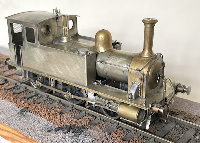
HR118 Chassis in progress 

My model of HR118 will illustrate the engine, as rebuilt by Sharp Stewart, towards the end of its service with the Highland Railway, when it had lost its former name, Gordon Castle, had its number plate removed and was working as a humble shunting engine. There's a photo of the engine at the end of its days, laid aside at Culloden Moor in 1923, in unlined olive green, which is a useful source for details of the engine; I won't make my model in quite as decrepit a state as this though. Only three photos of the engine are known to survive, along with a side elevation drawn by L Ward using the photos as reference. It's enough to build a model, though there are one or two details I don't understand to be resolved and I have no information at all on the cab interior.

There is no kit for this prototype in any scale so I'm scratch building it or, as I prefer to say, "modelling without the aid of a kit", though with reliance on the trade for suitable castings.  


Driving wheels are from Walsall Model Industries, these are cast iron, turned to size and drilled 12BA for the crank pins; they match the pattern of the prototype. The off-side drivers are insulated midway along the spokes. The frames are 0.7 n/s, set 26.6mm apart.


I made the coupling and connecting rods myself from 1.2 mm nickel silver sheet as I could find no trade source for this type of rod with marine big ends. The front crank pin seen here is a 10BA screw, the coupling rod runs in a brass bush and the connecting rod is held in place by a top hat bush threaded to match the screw. The slide-bars and cross-head are commercial castings of unknown provenance. A guard-plate will be fitted later behind the slide-bars, presumably this kept dirt away from the cross-head. The carrying wheels are held in place by a central keeper-rod, mounted on a transverse plate, which can be unscrewed to drop the wheels out of their slots.


The axle screw is inaccessible behind the slide-bars. The horizontal rod acts as a keeper for the carrying wheels which are easily removed from the frames. 

For detailed information on the prototype and its vicissitudes in service see...Cormack and Stevenson's Highland Railway Locomotives Bk.1, pubs. RCTS. 

Monday, 5 February 2024

LNWR Precedent...Merrie Carlisle


Renewed Precedent Class, Merrie Carlisle, LMS 5050 in 7mm scale 

The engine is built in nickle-silver, without the aid of a kit, though the tender is a Gladiator Models product, to which I made a few improvements. It is intended to finish the model in early LMS red, Merrie Carlisle being one of only four of this class to be turned out in full red passenger livery. When the engine first appeared in its new livery it carried number 5050 on a smokebox plate and retained its original socket lamp-irons. The Bill Finch Portfolio of Locomotive Details, published by the LNWR Society was an invaluable help in building the model. The only kit I know of for a Precedent is a Mercian Models product, which may no longer be in production.

Precedent chassis and mechanism revealed

Power is provided by an M1824 motor and ABC gearbox, mounted on the front driver and fitted with an MSC flywheel. I could have fitted a more powerful M1833, though there would not have been room for a flywheel. I prefer the smaller motor/flywheel set-up, which greatly enhances the engine's running qualities. Pick-ups are phosphor-bronze wire wipers on the left-hand wheels; the right-hand wheels are shorted by hidden wires. The front carrying wheels are from Slater's, who do not produce suitable Precedent driving wheels, those I used were supplied by JPL and may not be available now. 


Allan's straight link motion, simplified by the omission of the drop-links, fills the gap under the boiler. The valve rods pass through a gap in the motion plate. The sand boxes, which flank the motion plate, are filled with yellow Milliput.


The inside motion unit removed.

The tool box castings have been detailed and display how they were fastened to the tender top. 

Under the tender.

The water pick-up apparatus has not been included under the tender though the double brake pull-rods have been modelled fully. Note the tender buffers, which really work, being sprung behind the buffer beam. 

The Crew.


The loco crew are from my own sculpture and are cast in white metal in my workshop. Both figures are mounted on thin sheet metal bases and secured to the deck with double-sided tape. The fireman stands on the tender fall-plate, his base is made from scrap chequer-plate. The poses of the crew are designed so they relate to both the engine and to each other. They were designed as the model progressed and are an integral part of the model, by no means merely an afterthought.


The brakes are a tight fit.

A busy cab interior.


I built the cab interior with the help of castings from Laurie Griffin's range, most of which were modified in some way to suit a Precedent. I used Bill Finch's drawings for reference and don't think I left anything out. The roof, which is attached to the inner skin of the spectacle-plate, can be lifted off, which allows the back-head to be removed too. The spectacle-plate is double-skinned so the window glazing simply slips between the inner and outer skins. The prominent reversing wheel would have been better as a nickle-silver casting to approximate the steel original, but I could only get a brass one, I'm sure it'll look fine with the rim buffed up.

I heard recently that the "Master" himself, James Beeson, painted his reversing wheels red!


Friday, 26 January 2024

Some New Aids for 7mm Modellers.

New quality white metal castings from my own master patterns are now available for springs and axle-boxes to suit HR wagons. These can be ordered now price £5.50 per set (4 x springs & 4 x axle-boxes), illustrated below. Postage at cost £1.60 1st class or £1.15 2nd class.

The Jones wagon pictured is built from a set of of my own cast resin sides and ends. The availability of white metal springs and axle-boxes should make sourcing the castings and parts to complete these "aids to wagon building" easier. 


 Springs and grease type axle-box castings in white metal.
Note HR cast on the axle-box front plate


Jones open wagon, multi-media construction using Pete's resin sides and ends as a starting point.


Availability of "Aids to Wagon Building".

All sets of resin sides and ends are now available and are priced at £16.50 plus postage at cost £1.60 1st class or £1.15 2nd class. Buy 2 or more and post is free. Wagons built from these castings are featured in earlier posts on this blog.  

Drummond 8-ton 2-plank ballast wagon

Jones 15 foot 4-plank open wagon 

Drummond open fish truck with drop sides

7-ton swivel cradle wagon

Drummond 16-ton loco coal wagon

8-ton double-deck sheep van with planked sides 

Drummond 20-ton 6-wheel goods brake van (etched brass) £25

Also...HR wagon plate transfers 7mm scale £6

Contact...

armstrongps1@gmx.com

07342 637 813


Saturday, 20 January 2024

Duke of Sutherland's 4-wheel saloon in 7mm scale.

Duke of Sutherland's small 4-wheel saloon.


The duke of Sutherland's small saloon was built in 1908 by the Highland Railway at their Lochgorm works. After many travels and tribulations the coach, along with duke's locomotive Dunrobin, were repatriated from exile in Canada to Beamish in 2011. This event coincided with the production of a model of the coach by Lochgorm Kits in both 4mm and 7mm scales. The coach, beautifully restored to original condition, though with modified seating, is in service at the open air museum, the loco is still under restoration.  


Detail of the step end of the coach with glazing in place, castings are all brass and from various sources. 


The kit is not designed with an interior other than a lavatory enclosure in mind. The coach, as I've modelled it, is not intended to be viewed without the roof, the simplified interior gives an impression when seen through the glazing that the interior is fitted out. In earlier days there were armchairs and a table in the saloon end.


The service end had built-in seating and the corner units hide the bolt heads that secure the chassis to the superstructure. The interior is simplified, the lavatory compartment in reality is a particularly fine Victorian survival, modelling this would have been a minor work of art in itself.


The coach was built in three modules, a departure from the design of the kit, these were the roof, the body and the underframe or chassis. The coach body has had a floor added and is fixed to the underframe with four hidden screws, the roof is a neat friction fit into the body. Above you can see some of the hidden detail beneath the coach. The cast brass springs and their "J" hangers were particularly challenging to construct, the hard castings proving particularly resistant to efforts to drill through them. The ride height of the coach was increased by 2mm to allow space for the springs and axleboxes. The rocking-axle compensation system works well and the coach glides smoothly, though I question whether the bother involved in making this is worth the effort.
...

58A in 7mm scale painted by Paul Moore


The etched lavatory window was quite a challenge which took three of us to make. I thought the solution was a photo of the real thing, so I asked Paul Jarman at Beamish to take some photos for me. He took some photos in the shed where 58A is housed for the winter though the cramped situation of the coach made it difficult and the pictures needed some work on Photoshop which my daughter Alice, who knows about these things, managed in no time at all and printed them to size for the model. Paul Moore did the rest, mounting the print behind acetate to achieve what I think you'll agree is a most realistic result. The colour scheme of the coach matches that of my model of the duke's engine Dunrobin, which is in a private collection where 58A will shortly join it.


The duke's coach from the other side.